Ultra-sensitive strong laser power detection structure

A technology of strong laser and high power, which is applied in the field of detection structure of ultra-sensitive strong laser power, can solve the problems of inability to realize ultra-sensitive detection of strong laser and cannot directly apply strong laser, etc., and achieve the effect of high sensitivity

Inactive Publication Date: 2020-12-08
中山科立特光电科技有限公司
View PDF0 Cites 0 Cited by
  • Summary
  • Abstract
  • Description
  • Claims
  • Application Information

AI Technical Summary

Problems solved by technology

The traditional measurement of laser power is mainly based on the photoelectric effect or photothermal effect. Traditional laser power measurement methods cannot be directly applied to strong lasers, let alone achieve ultra-sensitive detection of strong lasers.

Method used


Image

  • Ultra-sensitive strong laser power detection structure
  • Ultra-sensitive strong laser power detection structure
  • Ultra-sensitive strong laser power detection structure

Examples


Embodiment 1

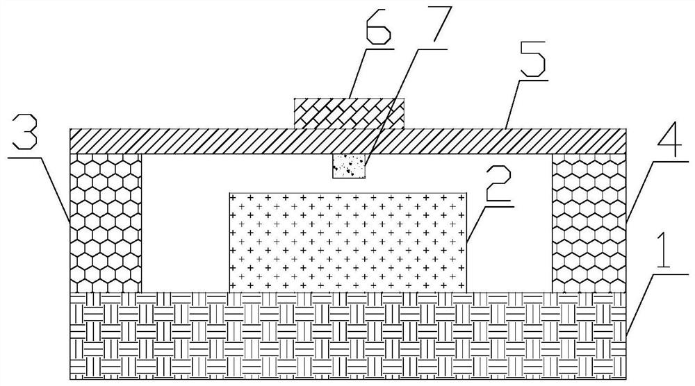
[0021] The invention provides an ultra-sensitive strong laser power detection structure. like figure 1 As shown, the ultra-sensitive strong laser power detection structure includes: a substrate 1 , a waveguide 2 , a first support portion 3 , a second support portion 4 , an elastic deformation layer 5 , a reflective layer 6 , and a sensing portion 7 . The waveguide 2 is placed on the substrate 1, and the material of the waveguide 2 is silicon dioxide. The material of the substrate 1 is magnesium fluoride. The first supporting part 3 and the second supporting part 4 are respectively placed on two sides of the section of the waveguide 2 . The first support part 3 and the second support part 4 are made of non-elastic material, and the materials of the first support part 3 and the second support part 4 are not limited here. The height of the first support part 3 and the second support part 4 is greater than that of the waveguide 2 , and the elastic deformation layer 5 is fixed o...

Embodiment 2

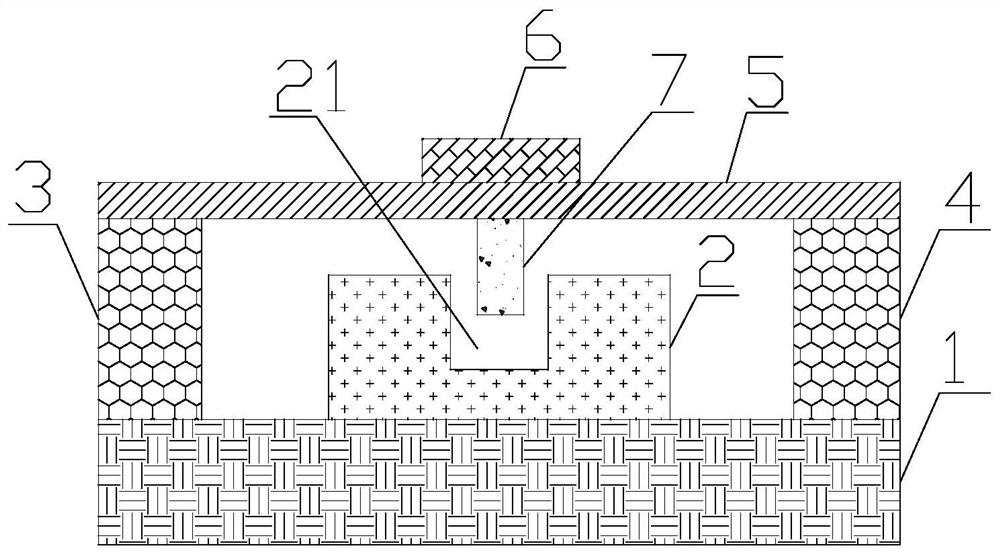
[0024] On the basis of Example 1, such as figure 2 As shown, the waveguide 2 is provided with a groove 21 , the sensing part 7 is placed above the groove 21 , and the width of the sensing part 7 is smaller than the width of the groove 21 . The material of the waveguide 2 is silicon dioxide. The material of the sensing part 7 is noble metal. When the elastic deformation layer 5 is deformed, the sensing part 7 can extend into the groove 21 . In this way, the sensing part 7 can change the propagation characteristics of the waveguide 2 more, thereby improving the sensitivity of detecting strong laser power. In this embodiment, the material of the waveguide 2 is silica, which is the same as the core material of an ordinary optical fiber, which is beneficial to reduce costs.

Embodiment 3

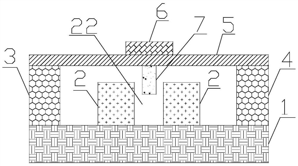
[0026] On the basis of Example 1, such as image 3 As shown, there is a slot 22 inside the waveguide 2 , the sensing part 7 is placed above the slot 22 , and the width of the sensing part 7 is smaller than the width of the slot 22 . The material of the waveguide 2 is silicon dioxide. The material of the sensing part 7 is noble metal. In this way, the sensing part 7 can penetrate more deeply into the waveguide 2, thereby changing the propagation characteristics of the waveguide 2 more, thereby improving the sensitivity of detecting strong laser power.


PUM

PropertyMeasurementUnit
thicknessaaaaaaaaaa

Abstract

The invention provides an ultra-sensitive strong laser power detection structure, which is characterized in that a reflecting layer is arranged on the upper surface of an elastic deformation layer, and a sensing part is arranged on the lower surface of the elastic deformation layer. During application, the continuous spectrum light source emits light and couples the light into the waveguide; whenstrong laser to be measured irradiates the reflecting layer, the elastic deformation layer deforms due to the fact that the strong laser generates force on the reflecting layer due to the photodynamiceffect, the distance between the sensing part and the waveguide is changed, the effective refractive index of the waveguide and the propagation characteristic of the waveguide are changed, and the optical detector is used for detecting the transmission coefficient of the waveguide. And the power of the to-be-measured intense laser is determined according to the change of the waveguide transmission characteristics. Since the propagation characteristic of the waveguide is very sensitive to the dielectric environment around the waveguide, the ultra-sensitive strong laser power detection structure has the advantage of high sensitivity of strong laser power detection.

Description

technical field [0001] The invention relates to the field of laser power measurement, in particular to a detection structure for ultra-sensitive strong laser power. Background technique [0002] Laser has a wide range of applications in communication, medical treatment, engineering technology and many other fields. In laser applications, accurate and real-time measurement of laser power is a key step. The traditional measurement of laser power is mainly based on the photoelectric effect or photothermal effect. Traditional laser power measurement methods cannot be directly applied to strong lasers, let alone achieve ultra-sensitive detection of strong lasers. Contents of the invention [0003] In order to solve the above problems, the present invention provides an ultra-sensitive strong laser power detection structure, including: a substrate, a waveguide, a first support portion, a second support portion, an elastic deformation layer, a reflective layer, and a sensing port...

Claims


Application Information

Patent Timeline
Patent Type & Authority Applications(China)
IPC IPC(8): G01J1/56
CPCG01J1/56
Inventor 不公告发明人
Owner 中山科立特光电科技有限公司
Why Eureka
Try Eureka