Bridge rigid segment model vibration measurement device for simulating oblique wind test condition in wind tunnel

A technology for test conditions and models, applied in the field of model vibration measuring devices for bridge rigid segments, can solve the problems of time-consuming and laborious adjustment of wind deflection angle, difficulty in achieving continuous adjustment, affecting the aerodynamic shape of the model, etc., and achieves easy adjustment and reduced design and manufacturing difficulty. , the effect of eliminating aerodynamic interference

Pending Publication Date: 2020-12-08
DALIAN UNIV OF TECH
View PDF0 Cites 2 Cited by
  • Summary
  • Abstract
  • Description
  • Claims
  • Application Information

AI Technical Summary

Problems solved by technology

The problems include: the adjustment of the windage angle is time-consuming and laborious, and it is generally difficult to achieve continuous adjustment; the bracket placed in the wind tunnel will interfere with the flow field; the local structure of the spring lifting point is usually welded or bolted, which will inevitably cause some damage to the wind tunnel; The local structure of the boom connecting the model and the spring is complex, and will affect the aerodynamic shape of the model, resulting in experimental errors

Method used


Image

  • Bridge rigid segment model vibration measurement device for simulating oblique wind test condition in wind tunnel
  • Bridge rigid segment model vibration measurement device for simulating oblique wind test condition in wind tunnel
  • Bridge rigid segment model vibration measurement device for simulating oblique wind test condition in wind tunnel

Examples


Embodiment Construction

[0018] The specific implementation manner of the present invention will be described in detail below in combination with the technical scheme and accompanying drawings.

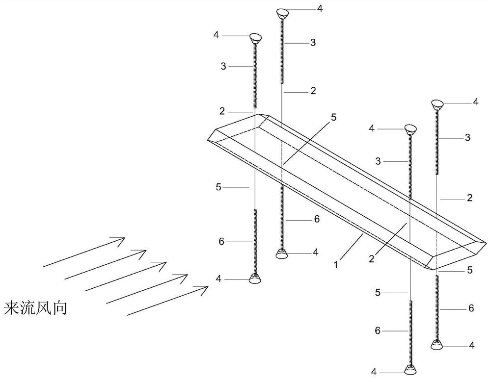
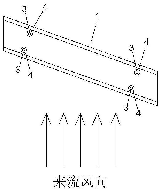
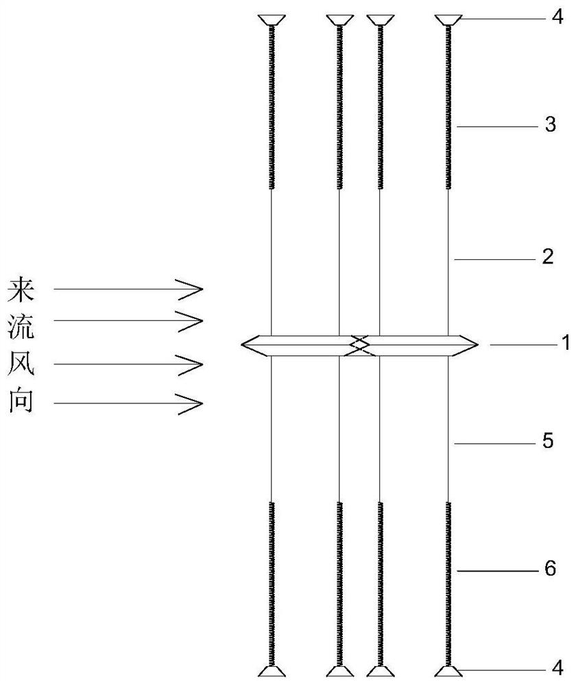
[0019] Such as figure 1 , figure 2 with image 3 As shown, the bridge rigid segment model vibration measuring device for simulating oblique wind test conditions in the wind tunnel includes the bridge rigid segment model 1, the first light and high-strength string 2, the first linear tension spring 3, the strong suction cup 4, The second lightweight high-strength thin rope 5 and the second linear tension spring 6; the two end faces of the rigid segment model 1 of the bridge are parallel to the wind direction and the side wall of the wind tunnel, so as to minimize the three-dimensional flow around the end; the rigid segment of the bridge The model 1 is connected to the lower end of the first linear tension spring 3 through the first light and high-strength string 2, and the upper end of the first linear tens...


PUM


Abstract

A bridge rigid segment model vibration measurement device for simulating inclined wind test conditions in a wind tunnel adopts an upper spring suspension system and a lower spring suspension system, and the positions of spring suspension points need to be adjusted along with wind deflection angles; upper and lower spring lifting points are fixed on a wind tunnel top plate and a wind tunnel bottomplate by strong suckers. And the spring is connected with the model through a light high-strength string. Under the condition that the normal incoming flow direction is kept in the wind tunnel, different wind deflection angles are achieved by adjusting the included angle between the longitudinal axis of the bridge model and the wind direction, and the two end faces are parallel to the wind direction and the wind tunnel side wall when the model is static. The device has the advantages that the windage yaw angle adjustment is simpler, more convenient and easier; no special bracket needs to be manufactured; no damage is caused to the wind tunnel; transverse lazy arms at the end parts of the model and connecting devices between the lazy arms and the model are canceled, so that the influence ofthe lazy arms on the aerodynamic load of the model is eliminated, and the model manufacturing difficulty is reduced; the suspension position of the model can be randomly selected as required withoutbeing limited at the end part, so that the rigidity requirement and the design difficulty of the model are reduced; and the device is lower in overall manufacturing cost and more practical.

Description

technical field [0001] The invention relates to a bridge rigid section model vibration measuring device for simulating oblique wind test conditions in a wind tunnel. The vibration measurement system composed of rigid segmental model, light and high-strength string, linear tension spring and strong suction cup can easily adjust the attitude of the model relative to the wind direction to meet Experimental conditions of different wind angles. Compared with the traditional oblique wind internal support bridge vibration test device, the advantages of this device include: easier adjustment of wind angle; no special vibration measurement support; no damage to the wind tunnel; no end transverse boom and connection The device not only eliminates aerodynamic interference, but also makes the model simpler; the suspension position of the model does not have to be limited to the end, and there can be partly symmetrical cantilevers at both ends, which reduces the span and lowers the rigidi...

Claims


Application Information

Patent Timeline
Patent Type & Authority Applications(China)
IPC IPC(8): G01M9/04G01M9/06G01M9/08
CPCG01M9/04G01M9/06G01M9/08
Inventor 许福友王品卿王博王骞
Owner DALIAN UNIV OF TECH
Why Eureka
Try Eureka