Gear positioning device, gear measuring device and measuring method
A technology of gear measurement and positioning device, which is applied in the direction of measuring device, testing of mechanical parts, testing of machine/structural parts, etc.
- Summary
- Abstract
- Description
- Claims
- Application Information
AI Technical Summary
Problems solved by technology
Method used
Image
Examples
Embodiment 1
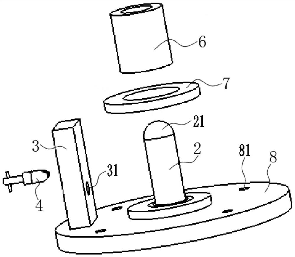
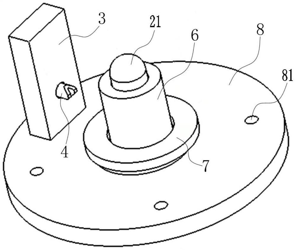
[0050] The invention provides a gear positioning device, such as Figure 1 to Figure 7 As shown, it includes a positioning shaft 2, a positioning column 3 and a locking pin 4. The shaft hole of the gear to be tested 1 is sleeved on the positioning shaft 2, so that the gear to be tested 1 is fixed on the plane. According to the size of the shaft hole of the gear to be tested 1, a bush 6 with a suitable size can be selected to be sleeved on the positioning shaft 2, so that the gear to be tested 1 is firmly fixed. A hemispherical alignment ball 21 is arranged on the top of the positioning shaft 2, and the center of the alignment ball 21 is located on the axis of the positioning shaft 2, which is convenient for determining the measurement center of the tooth to be measured.
[0051] Such as Figure 1 to Figure 7As shown, the positioning column 3 is arranged on one side of the gear 1 to be tested, and the positioning column 3 is provided with a locking groove 31 , and the locking...
Embodiment 2
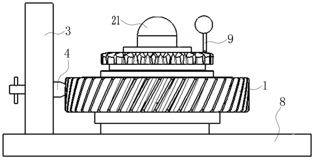
[0059] The present invention also provides a gear measuring device, such as Figure 3 to Figure 5 As shown, it includes a surface roughness profiler and the above-mentioned gear positioning device. The surface roughness profiler is provided with a workbench and a measuring needle 9 . The gear positioning device is installed on the workbench through the connecting hole 81 on the base 8, and the measuring pin 9 on the surface roughness profiler measures the gear 1 to be tested.
[0060] The stylus 9 is in contact with the teeth of the gear 1 to be tested, and transmits the contact information to the sensing parts on the main body of the surface roughness profiler. During the measurement process, the stylus 9 slides at a constant speed relative to the surface of the tooth of the gear 1 to be measured, so as to feel the geometric changes of the surface to be measured. The host computer of the surface roughness profiler converts the information sampled by the stylus 9 into electr...
Embodiment 3
[0063] The present invention also provides a gear measurement method, such as Figure 1 to Figure 10 As shown, use the gear measuring device described above. First, determine the transmission direction of the worktable of the surface roughness profiler as the Y direction, determine the axial direction of the positioning axis 2 as the Z direction, and determine the direction perpendicular to the Y direction and the Z direction as the X direction, that is, establish a three-dimensional structure about XYZ spatial coordinate system.
[0064] Then, the gear 1 to be tested is positioned and installed on the positioning shaft 2 . At this time, the gear 1 to be tested can be fixed by selecting bushes 6 , gaskets 7 , and pressing pieces with suitable quantities and sizes according to the specification of the gear to be tested 1 . When the number of gear teeth of the gear to be tested 1 is odd, the locking pin 4 is rotated, and the gear tenon 41 is inserted into the tooth groove of t...
PUM
 Abstract
Description
Claims
Application Information
 - R&D
- Intellectual Property
- Life Sciences
- Materials
- Tech Scout
- Unparalleled Data Quality
- Higher Quality Content
- 60% Fewer Hallucinations
Browse by: Latest US Patents, China's latest patents, Technical Efficacy Thesaurus, Application Domain, Technology Topic, Popular Technical Reports.
© 2025 PatSnap. All rights reserved.Legal|Privacy policy|Modern Slavery Act Transparency Statement|Sitemap|About US| Contact US: help@patsnap.com


