
In-situ bone taking and grafting indication guide plate in horizontal bone augmentation and manufacturing method thereof

A guide plate and incremental technology, applied in the direction of bone drill guidance, dental implantation, additive processing, etc., can solve the problems of affecting the surgical effect, increasing the surgical risk due to trauma, and the amount of bone harvested cannot meet the needs of bone grafting, etc., to improve the operation Efficiency, reduction of surgical trauma, simple and practical production method

Active Publication Date: 2020-12-11
SICHUAN UNIV
View PDF2 Cites 6 Cited by
  • Summary
  • Abstract
  • Description
  • Claims
  • Application Information

AI Technical Summary

Problems solved by technology

[0004] The technical problem to be solved by the present invention is: to provide an in situ bone harvesting and bone grafting indicator guide plate and its manufacturing method in horizontal bone augmentation, and to solve the problem that the amount of bone harvested in the prior art cannot meet the needs of bone grafting due to only empirical operations. Surgical effects, or technical problems of excessive bone harvesting causing additional trauma and increasing surgical risk

Method used


Image

  • In-situ bone taking and grafting indication guide plate in horizontal bone augmentation and manufacturing method thereof
  • In-situ bone taking and grafting indication guide plate in horizontal bone augmentation and manufacturing method thereof
  • In-situ bone taking and grafting indication guide plate in horizontal bone augmentation and manufacturing method thereof

Examples


Embodiment Construction

[0048] In order to make the objectives, technical solutions and advantages of the present invention clearer, the present invention will be further described in detail below with reference to the accompanying drawings. Obviously, the described embodiments are only some, but not all, embodiments of the present invention. Based on the embodiments of the present invention, all other embodiments obtained by those of ordinary skill in the art without creative efforts shall fall within the protection scope of the present invention.

[0049] In the description of the present invention, it should be noted that the terms "center", "upper", "lower", "left", "right", "vertical", "horizontal", "inner", "outer", etc. The indicated orientation or positional relationship is based on the orientation or positional relationship shown in the drawings, which is only for the convenience of describing the present invention and simplifying the description, rather than indicating or implying that the ...


PUM

PropertyMeasurementUnit
Thicknessaaaaaaaaaa
Thicknessaaaaaaaaaa

Abstract

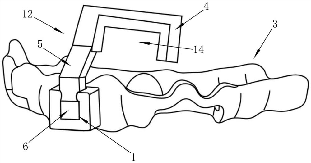
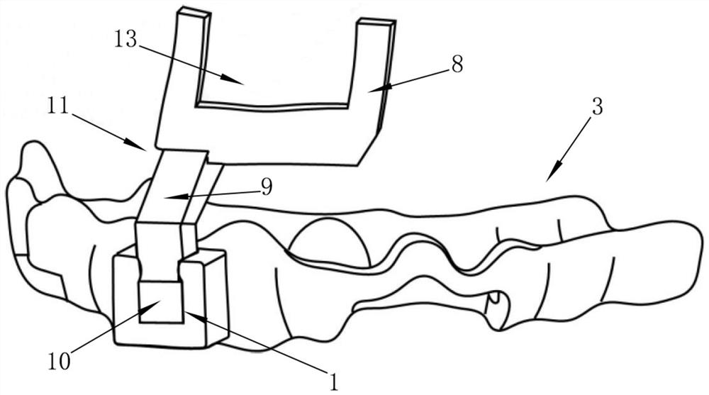
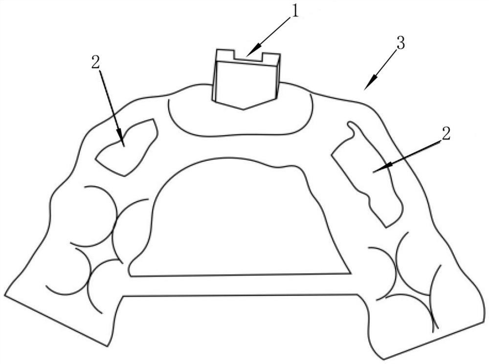
The invention discloses an in-situ bone taking and grafting indication guide plate in horizontal bone augmentation and a manufacturing method thereof. The technical problems that in the prior art, bone grafting requirements cannot be met during bone taking, the surgical effect is influenced, adjacent important vascular nerves and other anatomical structures are damaged due to inaccurate positioning of bone taking, or surgical risks are increased due to additional trauma caused by excessive bone taking are solved. The indication guide plate comprises a base plate, a bone shell obtaining guide plate and a bone shell placing guide plate. The manufacturing method mainly comprises the steps that stl data are obtained through oral scanning before an operation, CBCT is shot to obtain Dicom data,the two data are registered and fused to carry out ideal dental crown three-dimensional position design to obtain an ideal gingival margin position of a tooth loss area, ideal implant position designis carried out with repair as guidance, therefore horizontal bone augmentation final outer surface design is guided, and the base plate, the bone shell obtaining guide plate and the bone shell placingguide plate are designed. The three-dimensional positions of bone taking and bone grafting sites are accurately indicated, surgical wounds are reduced, surgical risks are reduced, the surgical time is shortened, complications such as damage to tooth roots of adjacent teeth are avoided, and the surgical efficiency is improved.

Description

technical field [0001] The invention belongs to the technical field of medical device structure, and in particular relates to an in-situ bone-grafting and bone-grafting indicating guide plate in horizontal bone augmentation and a manufacturing method thereof. Background technique [0002] When implant surgery is performed after a long period of tooth loss, there is often a problem of insufficient bone mass. For severe horizontal bone mass insufficiency, it is often necessary to perform bone augmentation first, and then perform implant surgery. The commonly used methods for horizontal bone augmentation There are Onlay bone grafts, GBR and more. Among them, in situ bone harvesting, obtaining the bone shell and then performing GBR for horizontal bone augmentation has been widely used in clinical practice. . In this bone augmentation technique, the routine procedure is to take the bone after roughly judging the extent of the bone defect during the operation, then fix the bone ...

Claims


Application Information

Patent Timeline
IPC IPC(8): A61B17/17A61C8/00B29C64/20B29C64/386B33Y30/00B33Y50/00G06T17/00
CPCA61B17/176A61C8/009B33Y30/00B33Y50/00B29C64/20B29C64/386G06T17/00
Inventor 满毅王婧屈依丽柳叶语李晗卿
Owner SICHUAN UNIV
Learn More