Automatic steel pushing and overturning device for profile steel

An automatic and section steel technology, applied in the field of metallurgy, can solve problems such as the inability to achieve effective flipping of rolled pieces, and achieve the effects of promoting the use, improving rolling rhythm, and eliminating collisions between rolled pieces and roller tables

Active Publication Date: 2020-12-11
MAANSHAN IRON & STEEL CO LTD
View PDF11 Cites 0 Cited by
  • Summary
  • Abstract
  • Description
  • Claims
  • Application Information

AI Technical Summary

Problems solved by technology

This device is mainly used for turning over the rolled pieces on the cooling bed, and cannot realize the effective turning of the rolled pieces during the rolling process.

Method used


Image

  • Automatic steel pushing and overturning device for profile steel
  • Automatic steel pushing and overturning device for profile steel
  • Automatic steel pushing and overturning device for profile steel

Examples


Embodiment 1

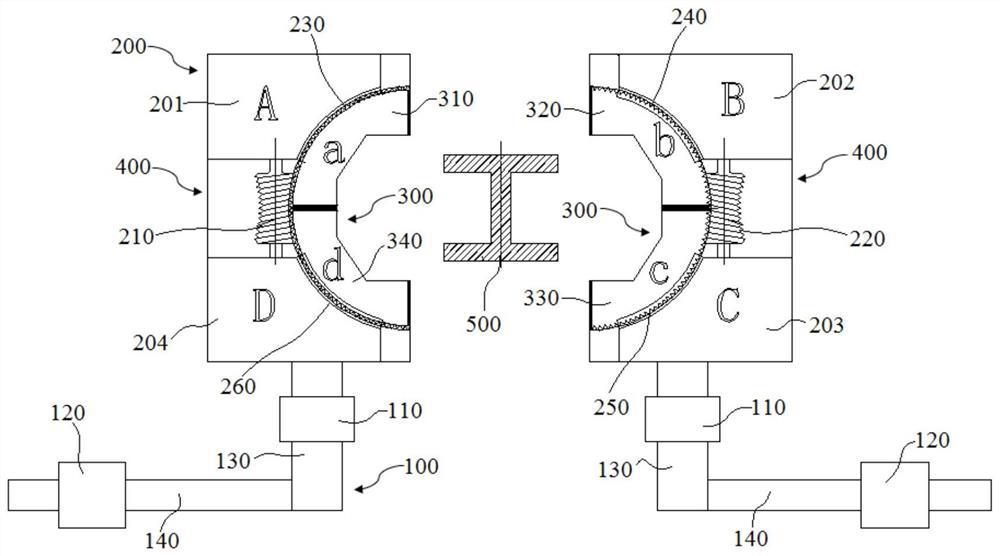
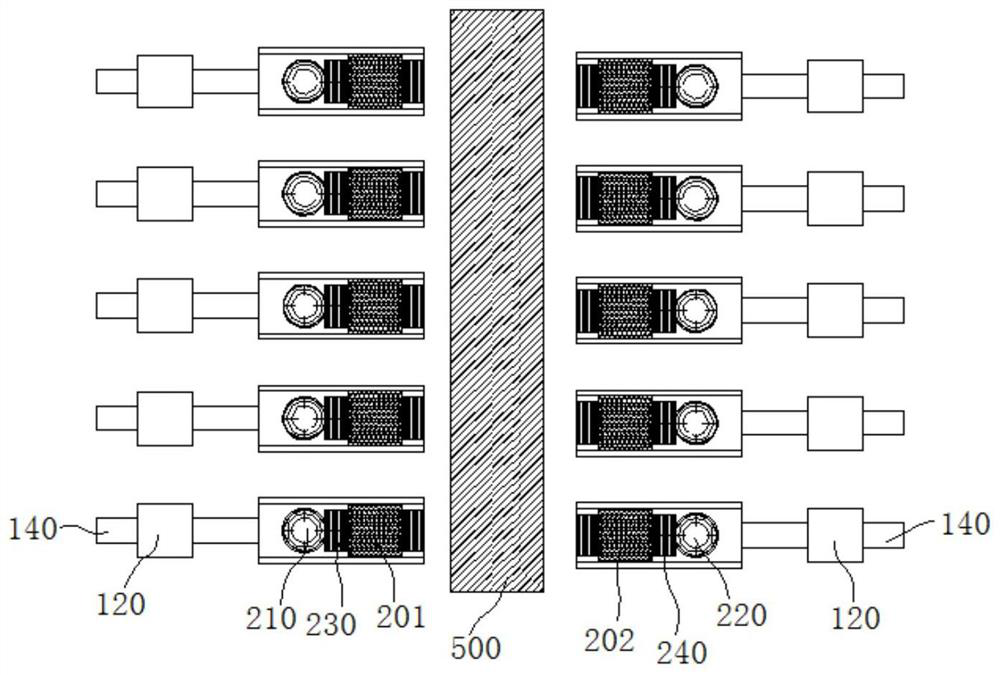
[0048] combine Figure 1-Figure 9 , a kind of automatic steel pushing-turning device for profiled steel of the present embodiment, comprises the left pushing steel-turning steel mechanism and the right pushing steel-turning steel mechanism of horizontal setting, described left pushing steel-turning steel mechanism and right pushing steel - The structure of the steel turning mechanism is the same, and it is distributed symmetrically. The left push steel-turn steel mechanism and the right push steel-turn steel mechanism are located at the same position and height, which is convenient to bite the rolled piece from both sides of the rolled piece, so as to ensure the subsequent pushing The stability of steel and turning steel action, and the left and right symmetrical structure design reduce the size and facilitate storage and use. Such as figure 1 As shown, the left push steel-turning steel mechanism in this embodiment includes a support unit 300 for clamping steel, an execution ...

Embodiment 2

[0054] A kind of section steel of present embodiment is used automatic push steel-turning steel device, and basic structure is identical with embodiment 1, further, as Figure 6 As shown, in this embodiment, the fixing part 270 includes a fixing part 271 connected to the bottom of the rotating gear. The center of the bottom of the fixing part 271 is provided with a push plate, and both sides of the bottom of the fixing part 271 are extended downward with positioning sections for positioning. The bottom of the segment is provided with a positioning protrusion 272 , the two ends of the positioning protrusion 272 in the width direction extend beyond the two ends of the positioning segment, and the pushing steel plate is located between the positioning protrusions 272 on both sides. The positioning projection 272 is used to fix the fixed part 270 and the rotating gear in the gear fixing groove as a whole, and there is a certain gap between the top of the rotating gear and the inner...

Embodiment 3

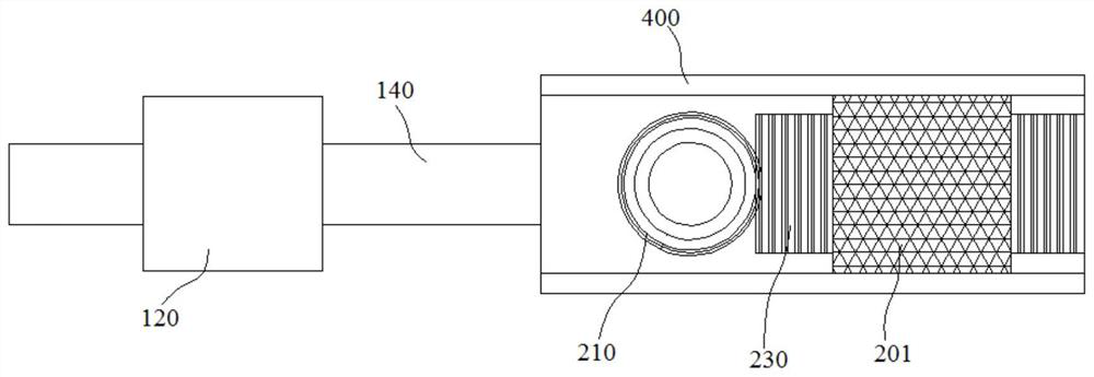
[0057] A kind of section steel of present embodiment is used automatic push steel-turning steel device, and basic structure is identical with embodiment 1, further, as figure 1 As shown, the displacement unit 100 in this embodiment includes a lifting push rod 130 arranged at the bottom of the execution unit 200, and a lifting hydraulic cylinder 110 is arranged on the lifting pushing rod 130. The lifting hydraulic cylinder 110 is used to control the left pushing steel-turning steel mechanism and The right push steel-turning steel mechanism lifts up and down to adjust the height position of the pushing steel-turning steel device; the bottom side of the lifting push rod 130 is provided with a translation push rod 140, and the translation push rod 140 is provided with a translation hydraulic cylinder 120, and the translation hydraulic cylinder 120 is arranged on the translation push rod 140. Cylinder 120 is used for controlling left push steel-turning steel mechanism and right push...


PUM


Abstract

The invention discloses an automatic steel pushing and overturning device for profile steel, and belongs to the technical field of metallurgy. The automatic steel pushing and overturning device comprises a left steel pushing and overturning mechanism and a right steel pushing and overturning mechanism which are horizontally arranged and symmetrically distributed, and the left steel pushing and overturning mechanism comprises a supporting unit, an executing unit and a displacement unit, the supporting unit is used for clamping the profile steel, the executing unit is used for controlling the supporting unit to rotate, and the displacement unit is used for controlling the supporting unit to move; and the supporting unit comprises two steel pushing plates which are arranged up and down and used for being matched with the section of the profile steel, the executing unit comprises two gear fixing grooves which are arranged up and down, fixing parts are arranged in the gear fixing grooves, rotating gears used for being in rotating fit with threaded lead screws are arranged at one ends of the fixing parts, and the other ends of the fixing parts are connected with the steel pushing plates.According to the automatic steel pushing and overturning device, the problems of centering and steel turning operation in the profile steel rolling process are solved, and not only can the steel turning angle be accurately controlled, but also rolled parts and contact equipment cannot be impacted.

Description

technical field [0001] The invention belongs to the technical field of metallurgy, and more specifically relates to an automatic steel pushing-turning device for shaped steel. Background technique [0002] With the development of domestic section steel, the types of section steel are gradually increasing, and U-section steel and other cross-sectional shapes are gradually added from the traditional H-section steel and I-section steel. In addition, with the development of the application field of section steel, the external dimension of section steel gradually develops towards the trend of large size and high meter weight (such as heavy H-section steel). For actual production, this development trend of section steel has brought certain difficulties to on-site operation and control. Due to the characteristics of rolling mill layout and pass design requirements in section steel rolling, centering and turning steps are performed on the rolled piece in the billet opening section ...

Claims


Application Information

Patent Timeline
Patent Type & Authority Applications(China)
IPC IPC(8): B21B39/24
CPCB21B39/24
Inventor 陈辉吴保桥夏勐吴湄庄沈千成汪杰黄琦邢军彦井成何军委彭林丁朝晖
Owner MAANSHAN IRON & STEEL CO LTD
Why Eureka
Try Eureka