Spherical valve core drilling machining device

A spherical spool and processing device technology, applied in feeding devices, metal processing, boring/drilling, etc., can solve problems such as hole position offset, small drill bit strength difference, affecting product performance, etc., to achieve accurate benchmark positioning, Easy loading and unloading, accurate indexing effect

Pending Publication Date: 2020-12-11
江西中船航海仪器有限公司
View PDF0 Cites 1 Cited by
  • Summary
  • Abstract
  • Description
  • Claims
  • Application Information

AI Technical Summary

Problems solved by technology

[0004] In view of the above situation, in order to overcome the defects of the prior art, the present invention provides a spherical valve core drilling processing device, which effectively solves the problem that the spherical valve core in the current market is the core component of a certain type of flow valve body, and the spherical surface of the spherical valve core The accuracy of the hole spacing directly affects the performance of the product. Generally, it is processed on a five-axis machine tool, but the cost is high. On the other hand, when drilling on a spherical surface, due to the small strength of the drill bit, it is easy to slip when the drill touches the spherical surface, making the hole position Offset occurs, and the hole spacing cannot meet the requirements of the pattern design

Method used


Image

  • Spherical valve core drilling machining device
  • Spherical valve core drilling machining device
  • Spherical valve core drilling machining device

Examples


Embodiment 1

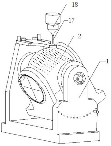
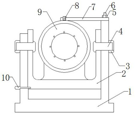
[0019] Embodiment one, by Figure 1-4 Given, the present invention includes a base 1, an azimuth frame 2 is fixedly installed on the top of the base 1, a pitch axis 4 is fixedly installed on both sides of the azimuth frame 2, and two pitch axes 4 are distributed around the axis center of the azimuth frame 2, The inside of the base 1 is provided with two through holes, and the two through holes are respectively inserted into the corresponding pitch axes 4, and one end of the two pitch axes 4 passes through the through holes and extends to the outside of the base 1. The sides are provided with several positioning holes, and several connecting holes are evenly distributed on both sides of the base 1, wherein the interior of the two positioning holes is movably inserted with a pitch positioning rod 10, and one end of the pitch positioning rod 10 is connected to the azimuth frame 2. Fixed insertion, the inside of the azimuth frame 2 is provided with a spherical valve core 9, and on...

Embodiment 2

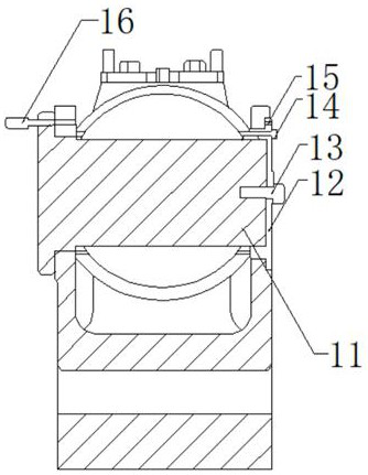
[0020] Embodiment 2, on the basis of Embodiment 1, the inside of the horizontal end cover 12 is fixedly connected with end cover screws 13 , and the horizontal shaft 11 is fixedly connected with the horizontal end cover 12 through the end cover screws 13 .

Embodiment 3

[0021] Embodiment 3, on the basis of Embodiment 1, a horizontal positioning pin 16 is movably inserted inside the base 1 , and one end of the horizontal positioning pin 16 is screwed with an anti-rotation screw 14 .


PUM


Abstract

The invention relates to the technical field of spherical valve core drilling, discloses a spherical valve core drilling device, and solves the problems that a spherical valve core on the market is acore part of a certain type of flow valve body at present, the hole spacing precision on the spherical surface of the spherical valve core directly influences the product performance, but the cost isgenerally higher when the spherical valve core is machined on a five-axis linkage machine tool, and on the other hand, due to the fact that a drill bit is small and poor in strength when drilling is conducted on the spherical surface, the drill bit is prone to slipping when the drill bit makes contact with the spherical surface, the hole position deviates, and the hole spacing cannot meet the requirements for pattern design. The spherical valve core drilling machining device comprises a base, wherein an orientation frame is fixedly arranged at the top of the base; pitching shafts are fixedly arranged on the two sides of the orientation frame; the two pitching shafts are distributed with the axis of the orientation frame as the center; and two through holes are arranged in the base. According to the spherical valve core drilling device, the drilling requirements for pattern design of parts are met, the indexing is accurate, the reliability is high, the batch machining, assembling and disassembling are convenient, and the benchmark positioning is accurate.

Description

technical field [0001] The invention belongs to the technical field of spherical valve core drilling, in particular to a spherical valve core drilling processing device. Background technique [0002] Drilling device refers to the general term for the equipment used to process holes on solid materials. Common drilling devices include electric drills, drilling machines, etc. With the further development of processing technology, the efficiency of drilling devices has also been greatly improved. [0003] However, the spherical valve core currently on the market is the core component of a certain type of flow valve body. The accuracy of the hole spacing on the spherical surface of the spherical valve core directly affects the product performance. Generally, it is processed on a five-axis linkage machine tool, but the cost is high. On the other hand, When drilling on a spherical surface, due to the small strength of the drill bit, it is easy to slip when the drill bit touches the...

Claims


Application Information

Patent Timeline
IPC IPC(8): B23B41/00B23B47/00B23B47/28B23B49/02B23Q7/02B23Q15/26B23Q16/02
CPCB23B41/00B23B47/00B23B47/287B23B49/02B23Q7/02B23Q15/26B23Q16/022
Inventor 李兵邱佩成刘平文维政卢俊李青周志刚
Owner 江西中船航海仪器有限公司
Why Eureka
Try Eureka