Polishing roll shaft based on ceramic home decoration polishing

A technology for polishing rollers and home furnishing, which is applied to machine tools for surface polishing, grinding/polishing equipment, and parts of grinding machine tools. Improve production rate and achieve efficient utilization

Inactive Publication Date: 2020-12-11
广州梦柯贸易有限公司
View PDF0 Cites 2 Cited by
  • Summary
  • Abstract
  • Description
  • Claims
  • Application Information

AI Technical Summary

Problems solved by technology

[0002] In the process of processing ceramic home accessories, in order to make the ceramic surface achieve a mirror finish, it is necessary to polish the ceramic surface. This process is called polishing and is an indispensable part. The existing ceramic polishing machine is in the process of polishing ceramics. Improper human operation will cause damage to the ceramic surface. At the same time, the long-term work of the machine itself will also cause errors, which will cause damage to the ceramics and even scrap them.
[0003] When the staff finds that there is an error in the machine and the operation is improper, the staff will cut off the connection between the motor and the power supply, but the roller shaft will continue to rotate for a period of time under the action of inertial force, which will cause the ceramics that can be remedied to be completely scrapped, resulting in Waste of resources, and the existing rotating roller shafts are all connected by rotating shafts, and their mass is relatively heavy. When rotating, the inner and outer shafts will generate friction, which increases the loss of the motor, which will cause waste of energy and reduce production rate.

Method used


Image

  • Polishing roll shaft based on ceramic home decoration polishing
  • Polishing roll shaft based on ceramic home decoration polishing
  • Polishing roll shaft based on ceramic home decoration polishing

Examples


Embodiment Construction

[0025] The following will clearly and completely describe the technical solutions in the embodiments of the present invention with reference to the accompanying drawings in the embodiments of the present invention. Obviously, the described embodiments are only some, not all, embodiments of the present invention. Based on the embodiments of the present invention, all other embodiments obtained by persons of ordinary skill in the art without making creative efforts belong to the protection scope of the present invention.

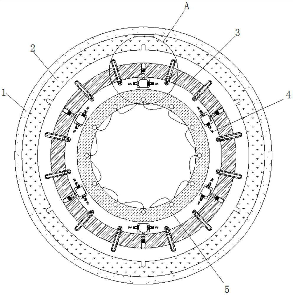
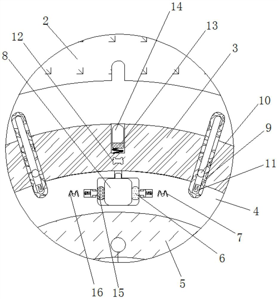
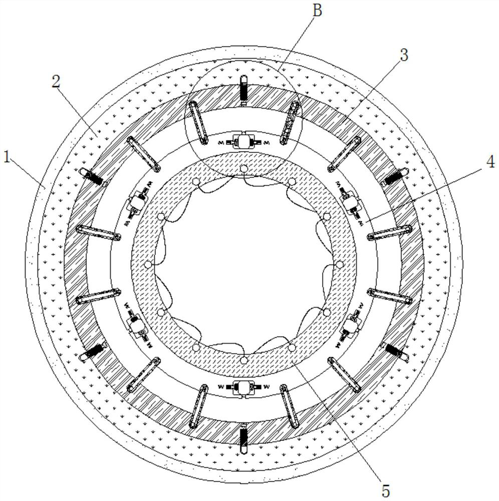
[0026] see Figure 1-4 , a polishing roller based on the polishing of ceramic home accessories, including a roller 1, the inner wall of the roller 1 is fixedly connected with a ferromagnetic ring 2, the inner side of the ferromagnetic ring 2 is movably connected with a rubber ring 3, and the diameter of the ferromagnetic ring 2 is Greater than the diameter of the rubber ring 3, the ferromagnetic ring 2 and the rubber ring 3 are cylindrical structures, the rubb...


PUM


Abstract

The invention relates to the technical field of home decorations, and discloses a polishing roll shaft based on ceramic home decoration polishing. The polishing roll shaft based on ceramic home decoration polishing comprises a roll shaft body, the inner wall of the roll shaft body is fixedly connected with a ferromagnetic ring, the inner side of the ferromagnetic ring is movably connected with a rubber ring, the inner wall of the rubber ring is movably connected with a fastening ring, and the inner wall of the fastening ring is fixedly connected with a closed wire magnetic ring. According to the polishing roll shaft based on ceramic home decoration polishing, a power source is switched on by the closed wire magnetic ring to drive the roll shaft body to rotate, efficient utilization of energy is achieved, the use of a motor is avoided, the production rate is increased, the power source is cut off, an ejected limiting block can be clamped into a clamping groove in the inner wall of the ferromagnetic ring to prevent the ferromagnetic ring from rotating, and therefore, rotation of the roller shaft is prevented, the roller shaft can stop rotating at the moment when a worker finds that amachine has errors and operation of the worker is improper and cuts off a power supply, damage and scrapping of ceramics are avoided, and resources are saved.

Description

technical field [0001] The invention relates to the technical field of home decorations, in particular to a polishing roller based on the polishing of ceramic home decorations. Background technique [0002] In the process of processing ceramic home accessories, in order to make the ceramic surface achieve a mirror finish, it is necessary to polish the ceramic surface. This process is called polishing and is an indispensable part. The existing ceramic polishing machine is in the process of polishing ceramics. Improper human operation will cause damage to the ceramic surface, and at the same time, the long-term work of the machine itself will also bring errors, which will cause ceramic damage or even scrapping. [0003] When the staff finds that there is an error in the machine and the operation is improper, the staff will cut off the connection between the motor and the power supply, but the roller shaft will continue to rotate for a period of time under the action of inertia...

Claims


Application Information

Patent Timeline
Patent Type & Authority Applications(China)
IPC IPC(8): B24B41/04B24B29/02
CPCB24B29/02B24B41/04
Inventor 陈治泰
Owner 广州梦柯贸易有限公司
Why Eureka
Try Eureka