Supercharge Your Innovation With Domain-Expert AI Agents!

Vacuum booster, brake booster control system and control method

A technology of vacuum booster and control system, applied in the direction of brakes, brake transmissions, vehicle components, etc., can solve the problems of system failure, difficult wiring, easy aging of wiring harnesses and connectors, and achieve the effect of optimizing the layout space of the engine room

Active Publication Date: 2021-11-23
DONGFENG MOTOR CORP HUBEI
View PDF7 Cites 0 Cited by
  • Summary
  • Abstract
  • Description
  • Claims
  • Application Information

AI Technical Summary

Problems solved by technology

[0003] The present invention provides a vacuum booster, a vacuum electronic pump control system and a control method to solve or partially solve the problem that the vacuum booster adopts a wire-connected vacuum pressure sensor, resulting in difficulty in wiring, easy aging of wiring harnesses and connectors, and system failure. Failed technical issues

Method used


Image

  • Vacuum booster, brake booster control system and control method
  • Vacuum booster, brake booster control system and control method
  • Vacuum booster, brake booster control system and control method

Examples


Embodiment Construction

[0037] In order to enable those skilled in the technical field to which the application belongs to understand the application more clearly, the technical solutions of the application will be described in detail below through specific embodiments in conjunction with the accompanying drawings. Throughout the specification, unless otherwise specified, terms used herein should be understood as commonly used in the art. Therefore, unless otherwise defined, all technical and scientific terms used herein have the same meaning as commonly understood by one of ordinary skill in the art to which this invention belongs. In case of conflict, this specification shall take precedence. Unless otherwise specified, various equipment used in the present invention can be purchased from the market or prepared by existing methods.

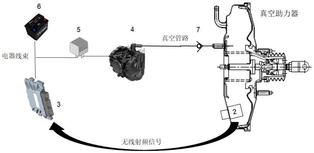
[0038] In order to solve the problem that the vacuum pressure sensor used on the existing automobile vacuum booster adopts cable connection to cause wiring difficulti...


PUM


Abstract

The invention discloses a vacuum booster. A vacuum pressure sensor is arranged on the housing of the vacuum booster. The vacuum pressure sensor comprises: an inner housing of the vacuum pressure sensor, which is fixedly connected to the inner surface of the vacuum booster housing and connected with the vacuum booster. The internal communication of the vacuum pressure sensor; the outer shell of the vacuum pressure sensor is fixedly connected to the outer surface of the vacuum booster shell and communicates with the external environment; the vacuum pressure sensor chip is set on the control circuit board, and the control circuit board is fixed on the inner shell of the vacuum pressure sensor Inside; the internal hollow antenna, one end is connected to the control circuit board, the other end is open and passes through the vacuum booster housing to enter the outer shell of the vacuum pressure sensor; the above-mentioned vacuum booster can transmit the internal and external pressure difference signal to the outside by wireless transmission. The transmission overcomes the difficulty in the layout of the engine cabin and the difficulty in the layout of the engine cabin, and the problems that the cables and connectors are prone to aging and failure, which leads to the failure of the power assist system.

Description

technical field [0001] The present application relates to the technical field of automobile manufacturing, in particular to a vacuum booster, a brake booster control system and a control method. Background technique [0002] At present, the brake booster system of most automobiles uses a vacuum booster. In order to detect the vacuum degree of the vacuum booster, an external vacuum pressure sensor with a cable is usually used, and the electrical signal collected by the sensor is transmitted to the controller through the wiring harness connection for analysis and calculation. , so as to indirectly control the work of the electronic vacuum pump; for example, it is clearly pointed out in CN104842987A: "The relative pressure sensor and the absolute pressure sensor pass three cables and the ground wire port, low-voltage power supply terminal, and signal transmission of the vehicle controller respectively. port connection". However, the environment of the engine compartment is com...

Claims


Application Information

Patent Timeline
Patent Type & Authority Patents(China)
IPC IPC(8): B60T13/72B60T13/52
CPCB60T13/52B60T13/72
Inventor 郝慧兵
Owner DONGFENG MOTOR CORP HUBEI
Features
  • R&D
  • Intellectual Property
  • Life Sciences
  • Materials
  • Tech Scout
  • Unparalleled Data Quality
  • Higher Quality Content
  • 60% Fewer Hallucinations
Learn More