Chassis supporting structure of hoisting machinery and crane

A technology for hoisting machinery and supporting structures, applied to cranes, mechanical equipment, springs/shock absorbers, etc., can solve problems such as cranes not working, booms in danger, inconvenient parts replacement, etc., to avoid tilting, Effect of reducing vibration and increasing area

Inactive Publication Date: 2020-12-11
TIANCHUANG ZHIKU CULTURE PROPAGATION SUZHOU CO LTD
View PDF0 Cites 1 Cited by
  • Summary
  • Abstract
  • Description
  • Claims
  • Application Information

AI Technical Summary

Problems solved by technology

[0003] The existing crane drives the boom through a hydraulic rod. When the hydraulic rod suddenly fails, the crane will not be able to work, which will affect the work progress and may cause the boom to drop suddenly and ca

Method used


Image

  • Chassis supporting structure of hoisting machinery and crane
  • Chassis supporting structure of hoisting machinery and crane
  • Chassis supporting structure of hoisting machinery and crane

Examples


Embodiment 1

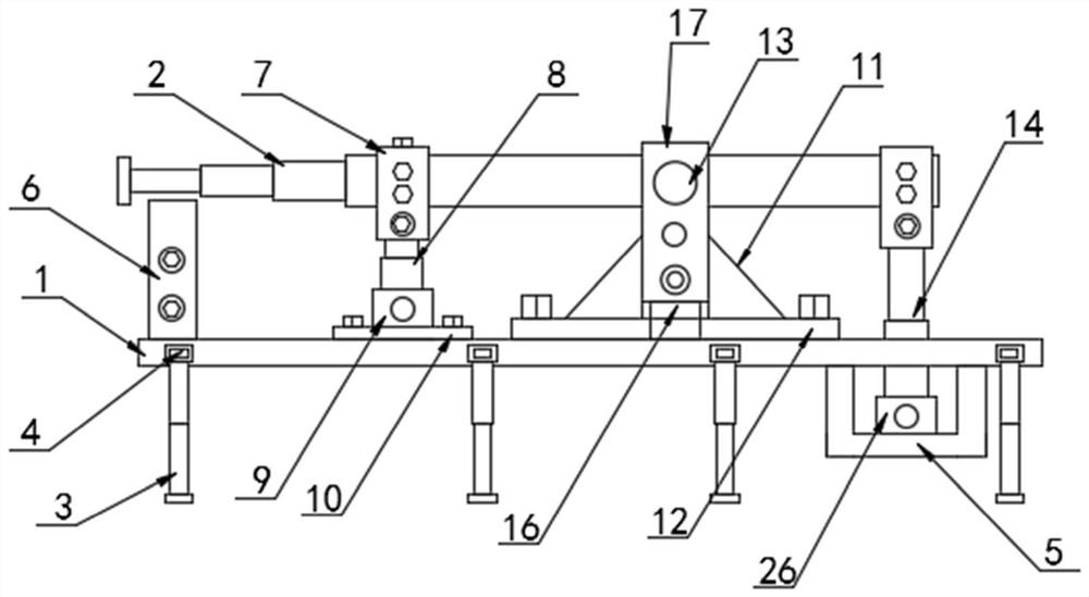
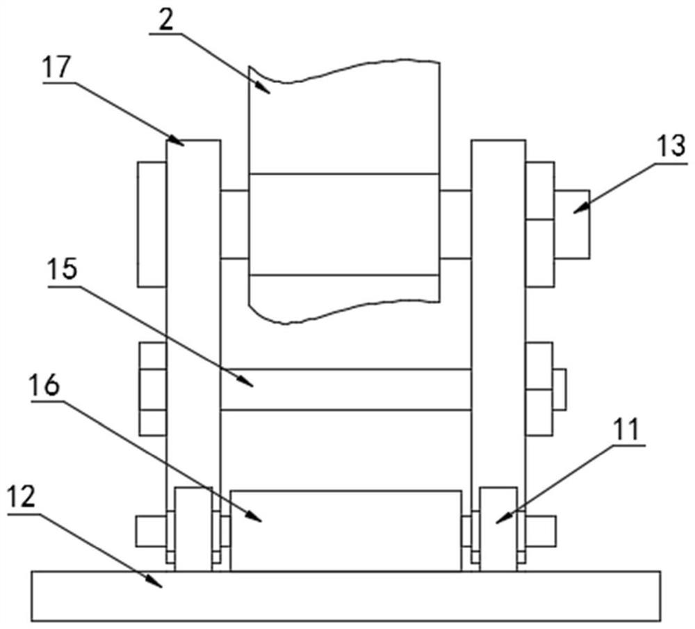
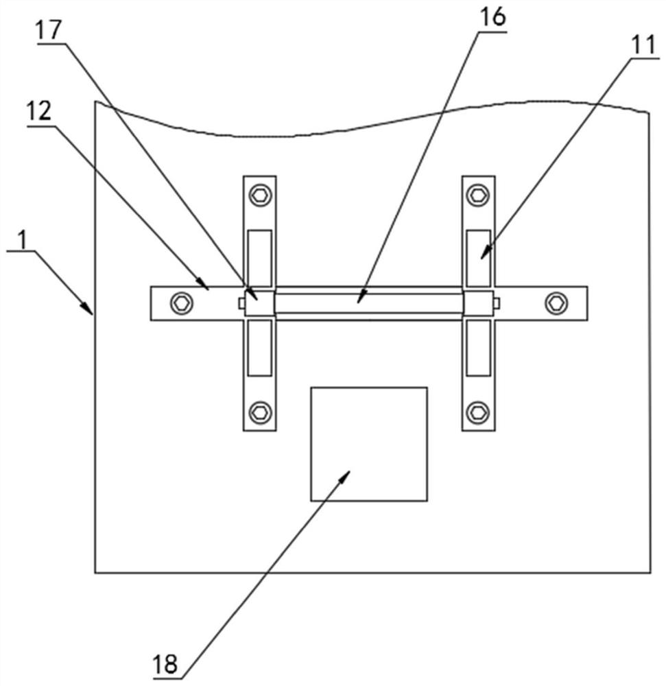
[0027] Refer to the attached Figure 1-5 In this embodiment, a chassis supporting structure of a hoisting machine and a crane include a chassis 1 and a boom 2, and first hydraulic rods 4 are fixedly installed at both ends of the chassis 1, and the bottom of one end of the first hydraulic rod 4 is fixed The second hydraulic rod 3 is installed, and the top of the left end of the chassis 1 is fixedly installed with a landing support 6, and one end of the landing support 6 is provided with a chute 23, and the landing support 6 is slidably connected to the landing support plate 21, and the landing support A buffer spring 22 is fixedly installed at the bottom of the plate 21, the bottom of the buffer spring 22 is fixedly installed on the top of the landing support seat 6, the top of the chassis 1 is fixedly connected to the support plate 10 by bolts, and the top of the support plate 10 is fixedly connected to the support seat One 9, the support seat one 9 is movably connected to the...

Embodiment 2

[0034] Refer to the attached Figure 6 , the difference from Embodiment 1 is that: the top of the landing support 6 is provided with a placement groove 25, and a buffer block 24 is arranged in the placement groove 25, and the buffer block 24 is made of fluorine rubber;

[0035] The specific implementation scenarios are:

[0036] Compared with Embodiment 1, when using the present invention, the extension of the first hydraulic rod 4 drives the second hydraulic rod 3 to expand outward, and the second hydraulic rod 3 is extended to touch the ground, so as to increase the contact point between the chassis 1 and the ground The formed area enhances the stability of the chassis 1. When the object needs to be hoisted, the first lifting hydraulic rod 8 is extended, and the left end arm sleeve 7 is pushed up, so that the left end of the boom 2 is raised, and the second lifting hydraulic pressure The rod 14 shrinks and pulls the right end arm cover 7 downward, and the right end arm cove...


PUM


Abstract

The invention discloses a chassis supporting structure of hoisting machinery, comprising a chassis and a cargo boom. First hydraulic rods are fixedly mounted at the two ends of the chassis; second hydraulic rods are fixedly mounted at the bottoms of one ends of the first hydraulic rods; a landing support base is fixedly mounted at the top of the left end of the chassis; a chute is formed in one end of the landing support base; the landing support base is slidably connected with a landing support plate; and a buffer spring is fixedly mounted at the bottom of the landing support plate. In the invention, the first hoisting hydraulic rods and the second hoisting hydraulic rods drive the cargo boom to move at the same time, so that the cargo boom rotates more quickly in a more labor saving mode; meanwhile, the first hoisting hydraulic rods and the second hoisting hydraulic rods are "spare tires" for each other; and when one hoisting hydraulic rod breaks down, the other hoisting hydraulic rod can drive the cargo boom, the use of the crane cannot be affected, and the left end of the cargo boom cannot be suddenly lowered to avoid dangers.

Description

technical field [0001] The invention relates to the technical field of cranes, in particular to a chassis support structure of a hoisting machine and a crane. Background technique [0002] Crane refers to the multi-action hoisting machinery that vertically lifts and horizontally transports heavy objects within a certain range, also known as crane, aerial crane, crane, and tire crane. 1. It is evolved from a crawler crane. The crawler and the walking frame of the walking mechanism are turned into a chassis with tires, which overcomes the shortcomings of crawler cranes that cause damage to the road surface. It belongs to material handling machinery. The hoisting equipment used for lifting and transporting materials over workshops, warehouses and stockyards, because its two ends are located on tall cement columns or metal supports, it is shaped like a bridge, and the bridge frame of the bridge crane is laid along the elevated bridges on both sides. The track runs longitudinall...

Claims


Application Information

Patent Timeline
IPC IPC(8): B66C23/06B66C23/80B66C23/82F16F15/08F16F15/067
CPCB66C23/06B66C23/80B66C23/823F16F15/067F16F15/085
Inventor 孙凤英
Owner TIANCHUANG ZHIKU CULTURE PROPAGATION SUZHOU CO LTD
Why Eureka
Try Eureka