
Energy-saving marine oil pollution cleaner

A technology for cleaners and oil stains, which is applied to the cleaning of open water surfaces, general water supply conservation, construction, etc., and can solve the problems of low treatment efficiency and small adsorption area

Active Publication Date: 2021-06-04
ZHEJIANG OCEAN UNIV
View PDF8 Cites 0 Cited by
  • Summary
  • Abstract
  • Description
  • Claims
  • Application Information

AI Technical Summary

Problems solved by technology

The present invention overcomes the deficiencies of the prior art and provides a cleaning structure specially used for sea surface oil pollution, which solves the problems of small adsorption area and low treatment efficiency of existing sea surface oil pollution

Method used


Image

  • Energy-saving marine oil pollution cleaner
  • Energy-saving marine oil pollution cleaner
  • Energy-saving marine oil pollution cleaner

Examples


Embodiment 1

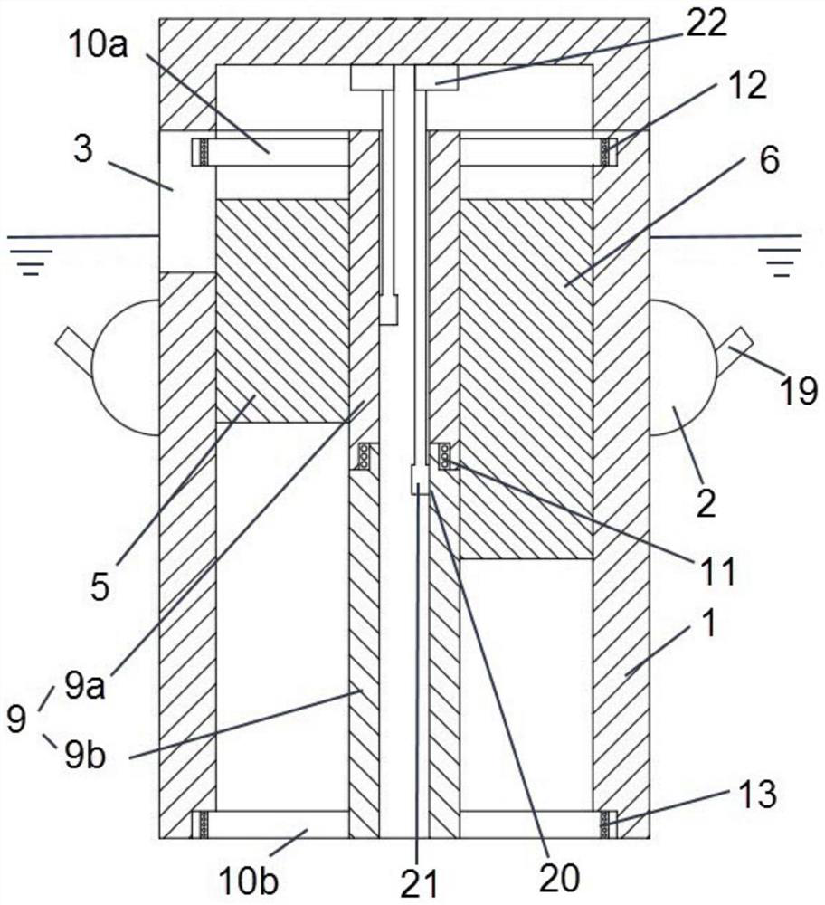
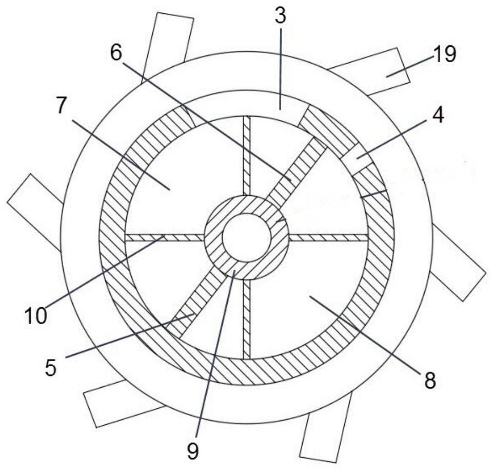
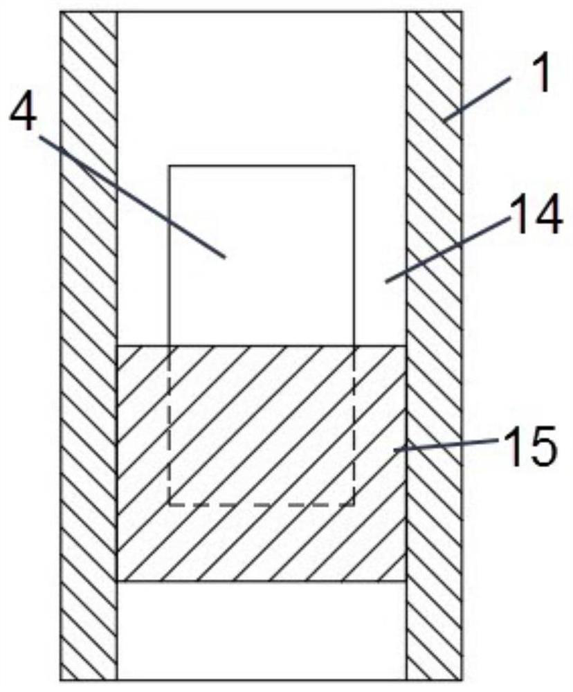
[0020] Such as Figure 1 to Figure 5 As shown, the present invention provides an energy-saving marine oil pollution cleaner, which at least includes a cleaning body 1 . The shape of the cleaning body 1 can be a hollow cylinder. A floating body 2 is arranged on the outer wall of the cleaning body 1 . The floating body 2 may be foam, an inflatable air bag, or the like. The cleaning body 1 can be made to float on the sea surface by setting the floating body 2 . The cleaning body 1 has a first oil inlet 3 and a first oil discharge 4 . Oil floating on the sea surface can enter the cleaning body 1 through the first oil inlet 3 and be discharged through the first oil outlet 4 . Through the above method, the oil stain can be surrounded by the cleaning body 1 , thereby reducing the risk that the oil stain will be captured under the sea surface and cannot be removed when the sea surface fluctuates.

[0021] The energy-saving marine oil pollution cleaner also includes a first oil di...

Embodiment 2

[0028] The energy-saving marine oil pollution cleaner of the present invention needs to be equipped with oil storage devices such as oil storage tanks when used. The oil storage device can float on the sea like a ship. The oil storage device can communicate with the first oil discharge port 4, and then the temporary storage of oil pollution can be realized through the oil storage device. A valve is arranged in the oil storage device. When the oil storage device is full, the valve closes automatically. The staff can collect and empty the storage device full of oil pollution through regular patrols, so as to realize its work again. For example, a liquid level sensor and a communicator are provided in the oil storage device. When the liquid level sensor detects that the liquid level is higher than the set value, it triggers the valve to close, and sends a wireless signal to the staff through the communicator to remind the staff that the oil storage device is full.

[0029] Th...


PUM


Abstract

The invention discloses an energy-saving marine oil pollution cleaner, which at least includes a cleaning body and a floating body, the floating body is arranged on the cleaning body so that the cleaning body can float on the sea surface, and the cleaning body is provided with a The independently rotatable first oil discharge push plate and the second oil discharge push plate separate the inner cavity of the cleaning body into a first area and a second area, and the cleaning body is provided with a first The oil inlet and the first oil discharge port communicated with the second area, the first oil discharge push plate and the second oil discharge push plate are arranged in an alternate rotation mode to continuously push the oil in the second area into the first oil discharge port. In a row of oil ports. After the oil on the sea surface enters the cleaning body from the first oil inlet, the cleaning body can block the waves on the sea surface. At this time, the oil that enters the cleaning body will not be shot into the seabed by the waves, and then enters the oil in the cleaning body Can be completely drained to improve oil cleaning efficiency.

Description

technical field [0001] The invention belongs to the technical field of environmental protection devices, and in particular relates to an energy-saving marine oil pollution cleaner. Background technique [0002] With the continuous occurrence of oil spill accidents at home and abroad in recent years, the problem of oil pollution in marine water is becoming more and more serious. When an oil spill occurs at sea, it will quickly spread on the sea surface to form an oil film. The oil film will isolate the oxygen in the air, which will suffocate a large number of organisms in the ocean, especially for marine fisheries. The traditional oil spill treatment method is the first measure to be taken after the oil spill accident occurs, and it is also the most commonly used method to deal with oil spill accidents. According to the different equipment used, it can be divided into the following three categories: physical treatment method, chemical treatment method, etc. Disposal and nat...

Claims


Application Information

Patent Timeline
Patent Type & Authority Patents(China)
IPC IPC(8): E02B15/10
CPCE02B15/10E02B15/107Y02A20/204
Inventor 潘昀刘灿沈良朵薛大文倪云林
Owner ZHEJIANG OCEAN UNIV
Learn More