Reinforced concrete frame column reinforcing structure and method

A technology of reinforced concrete and reinforced structure, applied in the direction of columns, piers, pillars, etc., can solve the problems of low stability and seismic resistance, and achieve the effects of high stability, improved seismic grade, and good shock absorption and buffer performance.

Active Publication Date: 2020-12-11
江苏苏建路桥机械有限公司
View PDF11 Cites 3 Cited by
  • Summary
  • Abstract
  • Description
  • Claims
  • Application Information

AI Technical Summary

Problems solved by technology

[0005] The purpose of the present invention is to provide a reinforced concrete frame column reinforcement structure and reinforcement method, which solves the problem of low stability and earthquake resistance of the frame column as the main load-bearing member of the house in the prior art

Method used


Image

  • Reinforced concrete frame column reinforcing structure and method
  • Reinforced concrete frame column reinforcing structure and method
  • Reinforced concrete frame column reinforcing structure and method

Examples


Embodiment 1

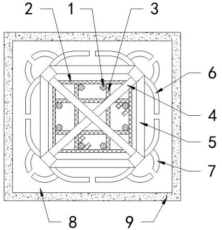
[0032] refer to Figure 1-3 , the reinforced structure of the reinforced concrete frame column, including the longitudinal bar 1 running through the frame column, the inner stirrup 2 and the outer stirrup 3 wrapped around the longitudinal bar 1, and the concrete filling area 8 and poured in the frame column The external wall panels 9 outside the concrete filling area 8 also include:

[0033] The built-in Bailey frame 4 is provided with two groups. The two groups of built-in Bailey frames 4 are crossed and fixed in an X shape along the diagonal of the frame column. The group is built into the Bailey frame 4;

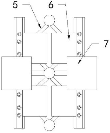
[0034] The external Bailey frame 5 is provided with four groups, and the four groups of external Bailey frames 5 are fixedly connected in pairs to form a square structure, and the two ends of the two sets of built-in Bailey frames 4 are fixedly connected in a square structure on the diagonal; the built-in Bailey frame 4, the external Bailey frame 5, the side spring boar...

Embodiment 2

[0038] refer to Figure 1-3 , the reinforcing method of reinforced concrete frame column, comprises the following steps:

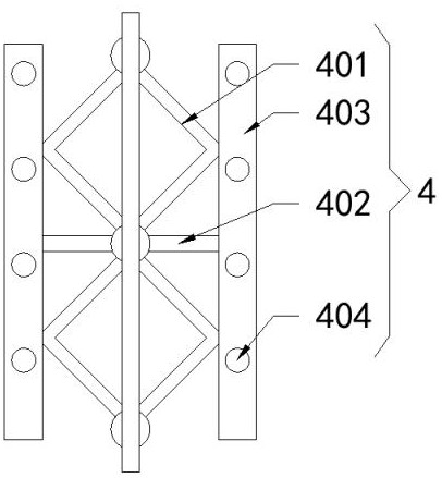
[0039] Step 1: After the two built-in Bailey frames 4 are arranged in an X-shaped cross, the square frames 401 of the two built-in Bailey frames 4 are welded, and then multiple groups of two built-in frames welded along the axis line of the frame column are welded. The Bailey frame 4 is inserted into the preset hole of the frame column, and the intersection point of the two built-in Bailey frames 4 is on the axis line of the frame column;

[0040] Step 2: Arrange the longitudinal reinforcement 1 in the preset hole of the frame column, and then connect the inner stirrup 2 and the outer stirrup 3 sequentially from the bottom to the top of the frame column, and the inner stirrup 2 runs through the two built-in Bailey frames 4 The square frame 401, the outer stirrups 3 run through the through holes 404 of the vertical frames 403 of the two built-in Bailey fra...


PUM


Abstract

The invention relates to a reinforced concrete frame column reinforcing structure and method. The problem that in the prior art, a frame column serving as a main bearing component of a house is low instability and shock resistance is solved. According to the reinforced concrete frame column reinforcing structure and method, the reinforced concrete frame column reinforcing structure comprises longitudinal bars penetrating through a frame column, inner stirrups, outer stirrups, a concrete filling area poured in the frame column and an outer wall plate attached to the outer portion of the concrete filling area, wherein the inner stirrups and the outer stirrups are connected to the outer portions of the longitudinal bars in a winding mode. The reinforced concrete frame column reinforcing structure further comprises a built-in bailey frame. According to the reinforced concrete frame column reinforcing structure and method, the frame column integrally uses the X-shaped crossed built-in bailey frame as a core shaft, the longitudinal bars penetrate through the frame column along the axis of the frame column, the inner stirrups and the outer stirrups are connected to the longitudinal barsand the X-shaped crossed built-in bailey frame in a winding mode, the built-in bailey frame is wrapped by the outer bailey frame, and therefore the two bailey frames form a stable triangular structure; and in addition, concrete pouring is conducted, and therefore the supporting force, the bending resistance and the pressure resistance of the frame column are all greatly improved.

Description

technical field [0001] The invention relates to a reinforcement structure and a reinforcement method of a reinforced concrete frame column. Background technique [0002] The reinforced concrete frame column is different from the structural column in the masonry structure: the structural column is a column set up to strengthen the wall and improve the integrity of the masonry structure. The structural column is used as a structural measure without force calculation; The main vertical member of the structure, frame-shear wall structure, is to bear all or the main vertical loads. Item 3.5.2 of the current "Code for Seismic Design of Buildings" (GB 50011) stipulates that the structural system "should avoid the loss of the seismic capacity of the entire structure or the bearing capacity of gravity load due to the damage of some structures or components". Therefore, for frame structures, The design of frame-shear wall structures generally follows the concept of "strong columns an...

Claims


Application Information

Patent Timeline
Patent Type & Authority Applications(China)
IPC IPC(8): E04B1/19E04B1/20E04C3/34E04B1/98E04H9/02
CPCE04B1/19E04B1/20E04C3/34E04B1/98E04H9/02
Inventor 杜玉兵蔡文华石飞停裴雪扬
Owner 江苏苏建路桥机械有限公司
Why Eureka
Try Eureka