Integrated steel connecting inserting plate and machining method thereof
A technology that integrates profile steel and processing methods, and is applied in construction and building construction to achieve the effects of simple operation, high construction efficiency, and improved construction convenience.
- Summary
- Abstract
- Description
- Claims
- Application Information
AI Technical Summary
Problems solved by technology
Method used
Image

Examples
Embodiment Construction
[0029] The technical solutions of the present invention will be further described below in conjunction with the accompanying drawings and through specific implementation methods.
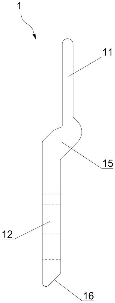
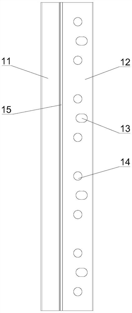
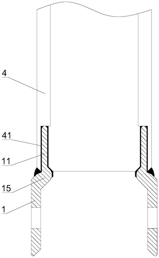
[0030] see Figures 1 to 5 As shown, this embodiment provides an integrated section steel connecting board, which includes a main body 1 of the board, on which a connecting part 11 and an assembly part 12 are arranged, and the connecting part 11 is fixedly connected to the end of the integrated section steel 4, Several installation holes are opened on the assembly part 12 , and bolts and / or bolts are used to pass through the installation holes of the two plugboard main bodies 1 to form the connection of the two integrated steel sections 4 .
[0031] The connection is more reliable when the bolt and the bolt act at the same time. According to the connection form of the bolt and the bolt, the mounting holes here are divided into bolt mounting holes 13 and pin mounting holes 14. It should be noted tha...
PUM
 Abstract
Description
Claims
Application Information
PatSnap Eureka turns technology decisions into work you can execute. Powered by our Innovation Knowledge Graph, it runs expert workflows across engineering, life sciences, materials and intellectual property. Get your review-ready output in minutes.


