Steel structure plane reinforcing structure

A technology for strengthening structures and steel structures, which is applied in building construction, building maintenance, construction, etc., can solve problems such as not being able to better deal with actual conditions, difficulty in achieving required strength, and potential safety hazards, and achieve a sense of user experience Good, good reinforcement effect, easy to operate effect

Inactive Publication Date: 2020-12-11
安徽春博环保科技有限公司
View PDF0 Cites 0 Cited by
  • Summary
  • Abstract
  • Description
  • Claims
  • Application Information

AI Technical Summary

Problems solved by technology

Since it is difficult to achieve the required strength when single-layer steel plate welding or bolt fastening is used for reinforcement, if multi-layer steel plates are to be welded, it will inevitably cause a substantial increase in load bearing and pose a safety hazard
Moreover, the reinforcement range of the current reinforcement structure is fixed and immutable, which makes it unable to better deal with the actual situation.

Method used


Image

  • Steel structure plane reinforcing structure
  • Steel structure plane reinforcing structure
  • Steel structure plane reinforcing structure

Examples


Embodiment 1

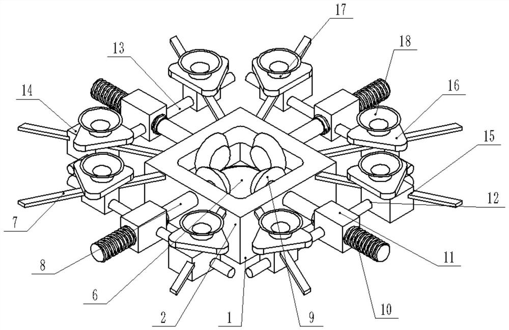
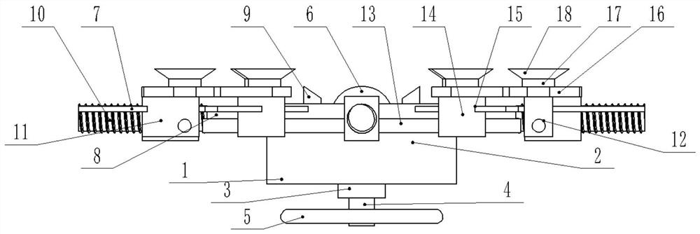
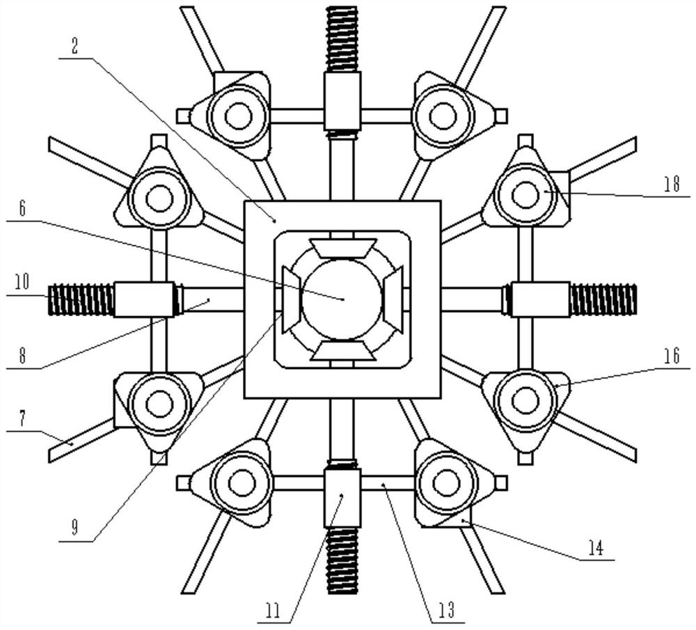
[0021] Example 1: Please refer to Figure 1-4 , a steel structure plane reinforcement structure, comprising a chassis 1, a box body 2 is fixedly connected above the chassis 1, a shaft sleeve 3 is fixedly connected below the middle part of the chassis 1, and the shaft sleeve 3 is rotatably connected with a rotating shaft 4, The bottom end of the rotating shaft 4 is fixedly connected with a control dial 5;

[0022] Turn the control dial 5 during use, and then make the rotating shaft 4 fixedly connected with the control dial 5 rotate, and then drive the driving bevel gear 6 fixedly connected with the rotating shaft 4 to rotate, and then make the driven bevel gear meshed with the driving bevel gear 6 9 rotates, and then drives the rotating rod 8 that is fixedly connected with the driven bevel gear 9 to rotate, and then drives the screw rod 10 that is fixedly connected with the rotating rod 8 to rotate, and then makes the moving block 11 that is threadedly connected with the screw ...

Embodiment 2

[0032] Embodiment 2: The difference between this embodiment and the previous embodiment is: please refer to Figure 1-4 , a steel structure plane reinforcement structure, comprising a chassis 1, a box body 2 is fixedly connected above the chassis 1, a shaft sleeve 3 is fixedly connected below the middle part of the chassis 1, and the shaft sleeve 3 is rotatably connected with a rotating shaft 4, The bottom end of the rotating shaft 4 is fixedly connected with a control dial 5;

[0033] Turn the control dial 5 during use, and then make the rotating shaft 4 fixedly connected with the control dial 5 rotate, and then drive the driving bevel gear 6 fixedly connected with the rotating shaft 4 to rotate, and then make the driven bevel gear meshed with the driving bevel gear 6 9 rotates, and then drives the rotating rod 8 that is fixedly connected with the driven bevel gear 9 to rotate, and then drives the screw rod 10 that is fixedly connected with the rotating rod 8 to rotate, and t...


PUM


Abstract

The invention discloses a steel structure plane reinforcing structure, and relates to a reinforcing device. The steel structure plane reinforcing structure comprises a chassis, a box body is fixedly connected above the chassis, a shaft sleeve is fixedly connected below the middle part of the chassis, the shaft sleeve is rotatably connected with a rotating shaft, and the bottom end of the rotatingshaft is fixedly connected with a control turntable; the steel structure plane reinforcing structure is characterized in that the top end of the rotating shaft is fixedly connected with a driving bevel gear; limiting plates are fixedly connected to the upper portion of the middle of the side wall of the box body in a front-back symmetry manner; plate grooves are connected with the limiting platesin a sliding manner; and a triangular supporting plate is fixedly connected to the upper portion of a sliding block, an air extractor is fixedly connected to the middle of the upper portion of the triangular supporting plate, and a suction cup is arranged at the air extraction end of the air extractor. Compared with a traditional reinforcing structure, the reinforcing structure has the advantagesthat the reinforcing range of the reinforcing structure can be adjusted, the reinforcing effect of the reinforcing structure is better, reinforcing is more uniform, and the reinforcing structure is simple in structure, convenient to operate and good in use experience.

Description

technical field [0001] The invention relates to a reinforcement device, in particular to a steel structure plane reinforcement structure. Background technique [0002] At present, in the reinforcement and transformation of steel structure buildings, the usual method is to add steel plates to the outside of the original structural parts for welding or to use high-strength bolts to reinforce them. Since it is difficult to achieve the required strength when single-layer steel plate welding or bolt fastening is used for reinforcement, if multi-layer steel plates are to be welded, it will inevitably cause a substantial increase in load bearing and pose a safety hazard. Moreover, the reinforcement range of the current reinforcement structure is fixed and immutable, which makes it unable to better cope with actual conditions. [0003] For this reason, those skilled in the art have proposed a steel structure planar reinforced structure to solve the problems raised in the above back...

Claims


Application Information

Patent Timeline
Patent Type & Authority Applications(China)
IPC IPC(8): E04G23/02
CPCE04G23/0218
Inventor 熊月春
Owner 安徽春博环保科技有限公司
Why Eureka
Try Eureka