Heat supply wear-resistant ball valve

A wear-resistant, ball valve technology, used in lift valves, valve details, valve devices, etc., can solve problems such as poor accuracy, aggravated rubber sealing ring wear, valve seat sealing ring damage, etc., to reduce wear and tear.

Active Publication Date: 2020-12-11
TEX TECH GRP LISHUI FLUID EQUIP CO LTD
View PDF7 Cites 2 Cited by
  • Summary
  • Abstract
  • Description
  • Claims
  • Application Information

AI Technical Summary

Problems solved by technology

A ball valve generally includes a valve body, a valve cover, a ball, a valve seat sealing ring, and a valve stem. The valve seat sealing ring is usually made of elastic materials such as rubber to form an elastic seal with the ball. However, during the rotation of the ball, the The edge of the through hole has sharp edges and corners. When the edges and corners contact the seat seal ring, it will cause wear or scraping that is not conducive to sealing, which will easily lead to damage to the seat seal ring, which greatly affects the sealing and life of the valve seat seal ring. Frequent replacement of the seat sealing ring affects the normal use of the ball valve, especially when the medium temperature is high, it will affect the strength of the rubber sealing ring and cause it to age, which will increase the wear of the rubber sealing ring; at the same time, the existing technology In the ball valve, the flow is adjusted by rotating the ball, the precision is poor, and fine flow control cannot be achieved.

Method used


Image

  • Heat supply wear-resistant ball valve
  • Heat supply wear-resistant ball valve
  • Heat supply wear-resistant ball valve

Examples


Embodiment Construction

[0021] The present invention will be further described in detail below in conjunction with the accompanying drawings and embodiments.

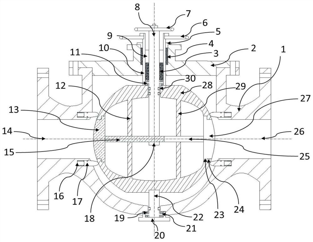
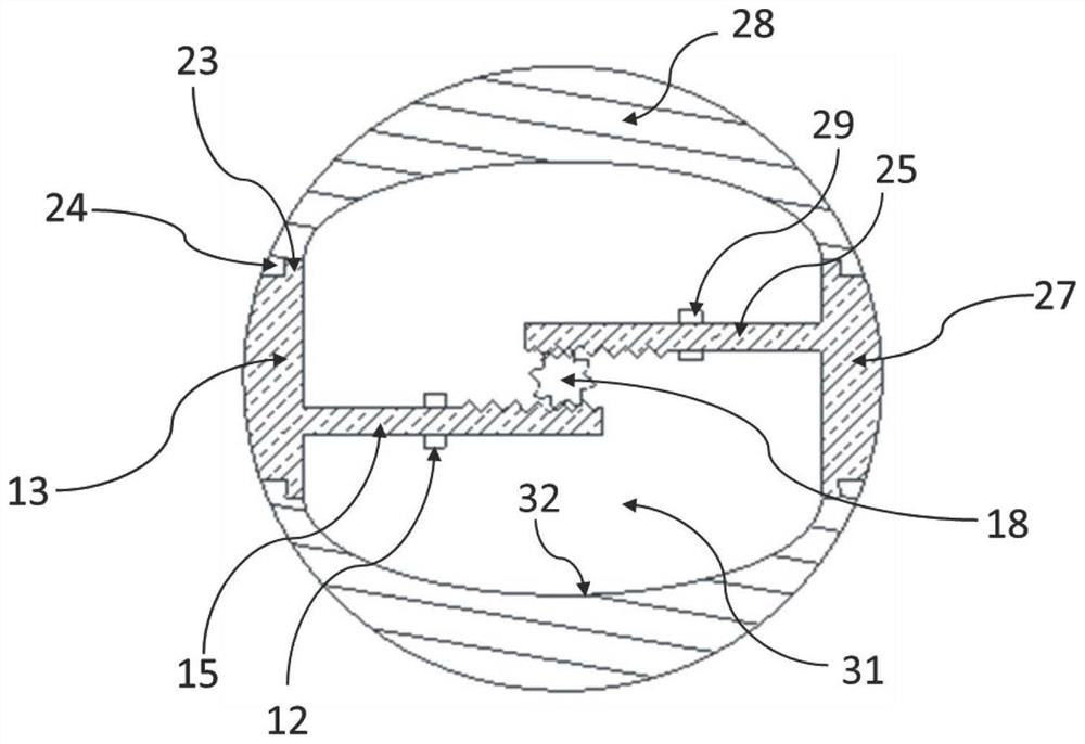
[0022] Such as figure 1 In the shown heat-supply wear-resistant ball valve, the valve body 1 has an inlet passage 14, an outlet passage 26, an upper opening, and a cavity between the inlet passage 14 and the outlet passage 26, and internal components such as a ball 28 and a valve seat can be Put into the middle chamber of the valve body 1 through the upper opening; the valve cover 2 is fixedly arranged on the top of the valve body 1 for closing the upper opening; the ball 28 is arranged in the middle chamber, and the inside of the ball 28 is provided with a ball inner chamber 31, and the ball 28 has The first through hole that communicates with the inlet channel 14 and the inner cavity of the ball 31 and the second through hole that communicates with the outlet channel 26 and the inner cavity 31 of the ball; the outer valve stem 10 is a hollow...


PUM


Abstract

The invention discloses a heat supply wear-resistant ball valve. The heat supply wear-resistant ball valve comprises a valve body, a valve cover, a ball body, an outer valve rod, an inner valve rod, avalve clack assembly and a second valve clack assembly, wherein the outer valve rod is fixedly connected with the ball body, the inner valve rod is in transmission connection with the first valve clack assembly and the second valve clack assembly, the outer surfaces of the first valve clack and the second valve clack are spherical surfaces, the diameter of the spherical surfaces is the same as the diameter of the outer surface of the ball body, and when the first valve clack and the second valve clack are in a completely closed state, the first valve clack and the second valve clack form a smooth spherical surface with the outer surface of the ball body, and when the first valve clack and the second valve clack are retracted into an inner cavity of the ball body, the fluid flow can be adjusted. According to the heat supply wear-resistant ball valve, when the two valve clacks are in a closed state, the outer surfaces of the valve clacks coincide with the outer surface of the ball body,so that a smooth curved surface is formed, edges and corners existing at a through hole of the ball body are eliminated, the ball body is prevented from scraping a valve seat sealing ring in the rotating process, the abrasion of the valve seat sealing ring is reduced, in the moving process of the valve clacks, the gap between the inner cavity wall of the ball body and the valve clacks is gradually increased, and fine adjustment of the valve flow is realized.

Description

technical field [0001] The invention relates to the technical field of ball valves, in particular to a heat-supply wear-resistant ball valve. Background technique [0002] Ball valves are a common type of valve used to control the opening and closing of fluid passages and are widely used in industrial fields. A ball valve generally includes a valve body, a valve cover, a ball, a valve seat sealing ring, and a valve stem. The valve seat sealing ring is usually made of elastic materials such as rubber to form an elastic seal with the ball. However, during the rotation of the ball, the The edge of the through hole has sharp edges and corners. When the edges and corners contact the seat seal ring, it will cause wear or scraping that is not conducive to sealing, which will easily lead to damage to the seat seal ring, which greatly affects the sealing and life of the valve seat seal ring. Frequent replacement of the seat sealing ring affects the normal use of the ball valve, espe...

Claims


Application Information

Patent Timeline
Patent Type & Authority Applications(China)
IPC IPC(8): F16K5/06F16K5/08F16K5/12F16K1/00F16K1/32F16K1/44F16K27/02F16K27/06F16K31/54F16K31/60
CPCF16K5/0605F16K5/0647F16K5/0694F16K5/0689F16K5/0684F16K5/08F16K5/12F16K1/00F16K1/32F16K1/44F16K27/02F16K27/067F16K31/54F16K31/60
Inventor 陈长青刘飞飞崔远明张晓明
Owner TEX TECH GRP LISHUI FLUID EQUIP CO LTD
Why Eureka
Try Eureka