Vertical pump bearing lubrication cooling device
A bearing lubricating and cooling device technology, applied in bearing elements, shafts and bearings, components of a pumping device for elastic fluid, etc. The effect of running, reducing the temperature
- Summary
- Abstract
- Description
- Claims
- Application Information
AI Technical Summary
Problems solved by technology
Method used
Image

Examples
Embodiment Construction
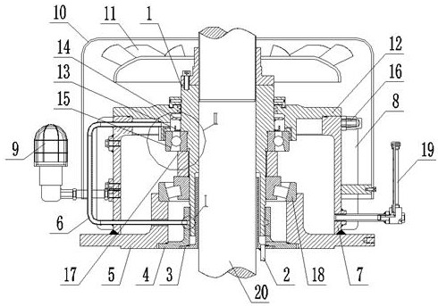
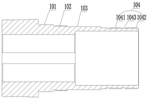
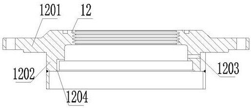
[0027] Such as Figure 1-Figure 5As shown, a kind of vertical pump bearing lubricating and cooling device of the present invention comprises shaft 20, bearing frame 5, overcoat 7, bearing gland 12, upper bearing 15, axle sleeve 17, lower bearing 18 and spiral sleeve 1, spiral sleeve 1 Connected to the shaft 20, the upper bearing 15, the shaft sleeve 17 and the lower bearing 18 are connected to the spiral sleeve 1, the bearing frame 5 is connected to the lower end of the lower bearing 18, the bearing gland 12 is connected to the upper end of the upper bearing 15, and the outer sleeve 7 is connected to the bearing frame 5 and the bearing gland 12, the upper bearing 15 and the lower bearing 18 are located in the outer casing 7, and the spiral sleeve 1 is provided with an upper bearing installation section 101, a threaded section 102, a lower bearing installation section 103 and an oil spinning section 104. The bearing installation section 101 is located above the threaded section...
PUM
 Abstract
Description
Claims
Application Information