
Intelligent automatic energy-saving drying equipment

A drying equipment and intelligent technology, which is applied in drying, drying machines, lighting and heating equipment, etc., can solve the problems of product quality reduction, cumbersome operation, heavy workload, etc., to reduce safety hazards and improve drying efficiency. Efficiency and the effect of reducing labor costs

Pending Publication Date: 2020-12-11
福建省宏禹节能环保科技有限公司
View PDF0 Cites 0 Cited by
  • Summary
  • Abstract
  • Description
  • Claims
  • Application Information

AI Technical Summary

Problems solved by technology

[0003] 1. In conventional drying equipment, materials and material trays need to be manually picked, placed and turned over regularly. The operation is cumbersome and the workload is heavy; automatic flow procedures cannot be realized;
[0004] 2. The material is exposed to the wind in one direction and cannot be evenly exposed to the wind, resulting in asynchronous drying of the material, and at the same time, it will cause changes in the color, shape and properties of the material to varying degrees, resulting in a large loss of nutrients and a reduction in product quality;
[0005] General drying equipment, the residual heat utilization system is relatively simple, the heat recovery rate is low, and the internal circulation humidity cannot be quickly adjusted according to the actual situation
[0006] 3. Ordinary drying equipment needs manual on-site inspection to see if the material has been dried. It cannot handle the material entering and leaving the warehouse in time, and problems such as equipment failure cannot be dealt with in time. If the equipment fails to stop running in time, it will cause fire hazards and other hidden dangers.

Method used


Image

  • Intelligent automatic energy-saving drying equipment
  • Intelligent automatic energy-saving drying equipment
  • Intelligent automatic energy-saving drying equipment

Examples


Embodiment Construction

[0027] The following will clearly and completely describe the technical solutions in the embodiments of the present invention with reference to the accompanying drawings in the embodiments of the present invention. Obviously, the described embodiments are only some, not all, embodiments of the present invention. Based on the embodiments of the present invention, all other embodiments obtained by persons of ordinary skill in the art without making creative efforts belong to the protection scope of the present invention.

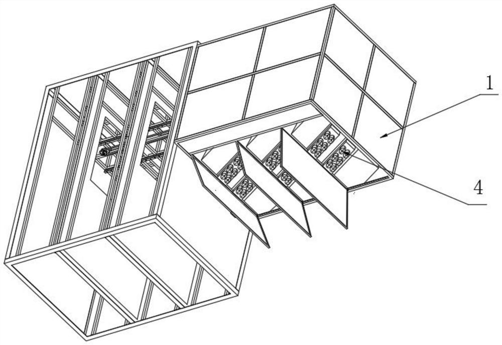
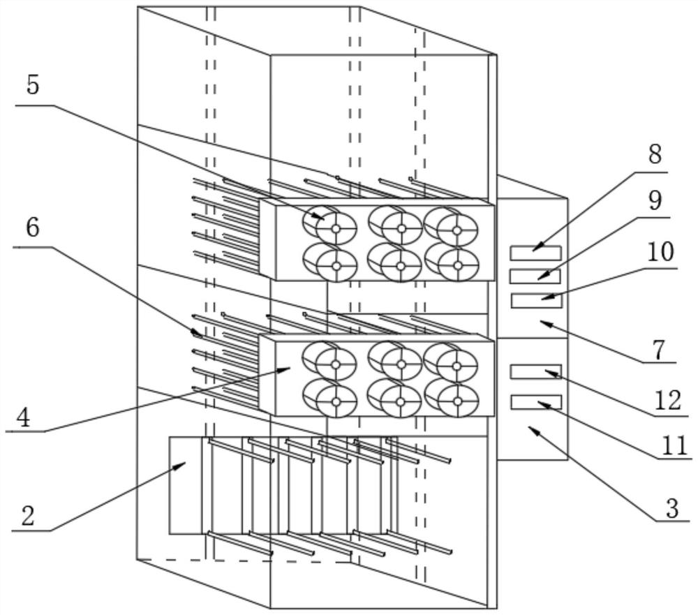
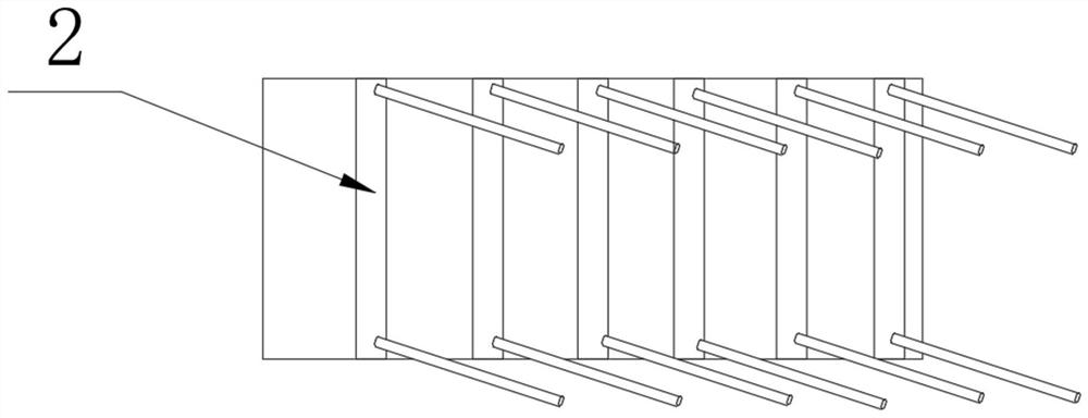
[0028] as attached Figure 1-5 The shown intelligent automatic energy-saving drying equipment includes a remote control system, a remote monitoring system, an automatic opening and closing door, a drying cabin body 1, and a material conveying mechanism 2, and the front side wall of the top of the drying cabin body 1 is installed There are PLC controllers and remote control system equipment. The middle part of the drying cabin 1 is horizontally fixed with two u...


PUM


Abstract

The invention discloses intelligent automatic energy-saving drying equipment, and particularly relates to the field of drying equipment. The intelligent automatic energy-saving drying equipment comprises a remote control system, a remote monitoring system, an automatic opening and closing door, a drying cabin, a material conveying mechanism and automatic flow equipment, and a PLC and remote control system equipment are installed on the front side wall of the top of the drying cabin; an upper partition plate and a lower partition plate are horizontally fixed to the middle of the drying cabin, aplurality of flow dividing boxes are installed on one side of each partition plate at equal intervals, one end of each flow dividing box communicates with the output end of an air feeder, and a frequency converter is installed at the input end of each air feeder; and a truss is arranged on the front side of the drying cabin, a motor is fixed to one side of the interior of the truss, and an automatic conveying mechanism is horizontally arranged at the top of the truss. According to the intelligent automatic energy-saving drying equipment, a rotating shaft is driven by the motor, so that the conveying mechanism rotates at a constant speed, material trays can be conveniently pushed back and forth between a cabin door and a conveying belt body, and the material taking and placing efficiency is improved.

Description

technical field [0001] The invention relates to the technical field of drying equipment, and more specifically, the invention relates to an intelligent automatic energy-saving drying equipment. Background technique [0002] Most of the existing drying equipment adopts the method of air outlet from top to bottom or side air, and only simple parts (including frame structure, fan system, heating element, etc.) are set in the dryer. There are often the following problems: [0003] 1. In conventional drying equipment, materials and material trays need to be manually picked, placed and turned over regularly. The operation is cumbersome and the workload is heavy; automatic flow procedures cannot be realized; [0004] 2. The material is exposed to the wind in one direction and cannot be evenly exposed to the wind, resulting in asynchronous drying of the material, and at the same time, it will cause changes in the color, shape and properties of the material to varying degrees, resul...

Claims


Application Information

Patent Timeline
IPC IPC(8): F26B9/06F26B21/00F26B21/04F26B25/00
CPCF26B9/06F26B21/002F26B21/004F26B21/04F26B25/00F26B25/003
Inventor 苏楠
Owner 福建省宏禹节能环保科技有限公司
Learn More