
Energy conservation control device for power transmission

A technology of energy-saving control and power transmission, which is applied to the arrangement of multiple prime movers of power plants, pneumatic power plants, and general power plants, and can solve the problems of low engine efficiency

Active Publication Date: 2013-10-02
陆云飞
View PDF8 Cites 3 Cited by
  • Summary
  • Abstract
  • Description
  • Claims
  • Application Information

AI Technical Summary

Problems solved by technology

[0006] In order to solve the problem of low working efficiency of the above-mentioned engine, the present invention introduces energy storage loads, namely generators, storage batteries, motors and energy storage controllers, to adjust, absorb, store and release the output energy of the engine, in order to achieve the best engine performance. conditions, including several types of fixed power pre-selected or shutting down the engine, to achieve the purpose of high efficiency, energy saving and emission reduction

Method used


Image

  • Energy conservation control device for power transmission
  • Energy conservation control device for power transmission
  • Energy conservation control device for power transmission

Examples


Embodiment 1

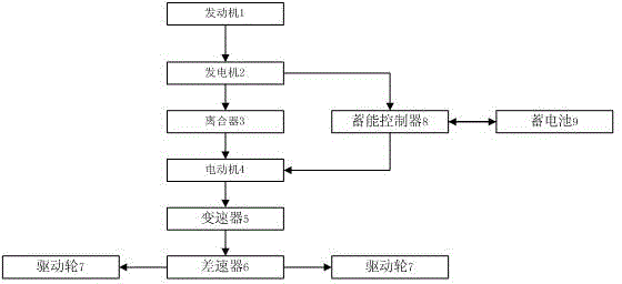
[0050] A typical embodiment of the present invention is composed of engine 1, generator 2, clutch 3, motor 4, speed changer 5, differential 6, drive wheel 7, and the energy storage controller 8 is connected with generator 2 and motor 4 respectively. , accumulator 9, refer to figure 1 shown.

[0051] When the vehicle starts, the clutch 3 is in a disengaged state, and the motor 4 drives the input shaft of the transmission 5, which is transmitted to the output shaft through the relevant gear position of the transmission 5, and drives the vehicle to start running. When the energy output of the storage battery 9 drops to the lower limit of its design capacity, the engine 1 is started and the clutch 3 is engaged. At this time, the output power of the engine 1 is determined by the position of the working stroke of the accelerator pedal, which is in one of the two (or more than two) pre-selected working conditions. Due to the existence of the generator in the energy storage load, re...

Embodiment 2

[0055] In this embodiment, since the energy storage load is essentially an electric or hydraulic transmission system, the transmission in the vehicle is replaced with an epicyclic differential gear train, and various stepless adjustments desired when the vehicle is running can be obtained. The speed ratio of the transmission can reduce the volume and weight of the gearbox, and reduce the cost of vehicle manufacturing and maintenance.

[0056] like figure 2 As shown, the flow diagram of the power transmission of the second embodiment of the present invention is sequentially connected by the engine 1, the generator 2, the clutch 3, the epicyclic differential gear train 10, the differential 6, and the drive wheel 7, and the energy storage controller 8 A generator 2 , an electric motor 4 , and a storage battery 9 are connected, and the electric motor 4 is connected to an epicyclic differential gear train 10 .

Embodiment 3

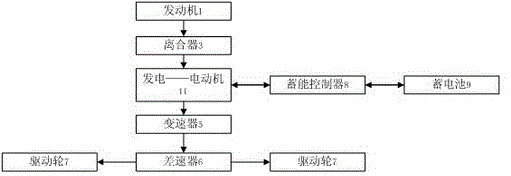
[0058] In this embodiment, the generator and the motor are replaced by a combined generator and motor. like image 3 As shown, it is a schematic flow chart of power transmission in this embodiment. The engine 1, clutch 3, generator-motor 11, transmission 5, differential 6, and drive wheels 7 are sequentially connected, and the energy storage controller 8 is connected to the generator-motor. 11. Battery 9.

[0059] During the working process of this embodiment, the engine remains in an idling operating condition to meet the shifting requirements of the transmission. When the vehicle is stationary, if the transmission is placed in a neutral position, all the output power of the engine is used for the generator, and the converted energy is delivered to the storage battery for storage.


PUM


Abstract

The invention provides an energy conservation control method and device for power transmission and particularly relates to the field of hybrid power vehicles. The energy conservation control device is an energy conservation control device for hybrid power transmission and comprises a generator, a storage battery, a motor and a clutch. The energy conservation control device is characterized in that an energy storage controller is also included, and the generator, the storage battery, the motor and the energy storage controller form an energy storage load, wherein a rotating shaft of the generator is connected in series between and engine and an input shaft of the clutch, the motor is connected in series between an output shaft of the clutch and an input shaft of a speed changer, the power output end of the generator is connected with the input end of the energy storage controller, the output end of the energy storage controller is connected with the storage battery which is connected to the motor through the energy storage controller, and the output end of the speed changer drives driving wheels on two sides through a differential mechanism. The energy conservation control device has the advantages that the output energy of the engine is adjusted and released through storage of the energy storage load, the engine is made to achieve the best working condition, and the effect of efficient energy conservation and emission reduction is achieved.

Description

technical field [0001] The invention relates to an energy-saving method and device for automobile power, in particular to an energy-saving control method and device for hybrid power transmission of vehicles. Background technique [0002] In the existing technology, energy saving and environmental protection of automobiles have become the mainstream of the development of the automobile industry, and hybrid electric vehicles have become the key core technology for the development of various countries. [0003] The application number is the Chinese invention patent of CN03102153.0, and the name is called: "parallel hybrid power transmission unit", discloses the hybrid power transmission unit of the automobile. The hybrid power transmission unit refers to an internal combustion engine, etc., a fuel-powered power system and an electric motor or a generator, that is, a fuel-powered power system and an electric-driven power transmission unit are installed in the same power transmis...

Claims


Application Information

Patent Timeline
IPC IPC(8): B60K6/28B60K6/20B60K6/50B60W20/00B60W10/06B60W10/08B60W10/26B60W20/10
CPCY02T10/62
Inventor 陆云飞林绍秋
Owner 陆云飞
Learn More