Vacuum oil injection structure of large oil-immersed transformer and oil conservator and working method of vacuum oil injection structure

An oil-immersed transformer and oil-filling structure technology, applied in the direction of transformer/inductor cooling, etc., can solve the problems of high partial discharge of the transformer, inability to fill part of the oil conservator with vacuum oil, insufficient degassing of the transformer oil, etc., so as to prevent the suction of the vacuum pump. , to ensure the effect of work reliability

Pending Publication Date: 2020-12-11
FUZHOU TIANYU ELECTRIC
View PDF0 Cites 0 Cited by
  • Summary
  • Abstract
  • Description
  • Claims
  • Application Information

AI Technical Summary

Problems solved by technology

[0002] In the vacuum oil filling process of traditional large oil-immersed transformers, only the oil tank part of the transformer can be vacuum oil filled, but the oil conservator part cannot be vacuum oil filled, resulting in insufficient degassing of the transformer oil in the oil conservator part, and further Make the partial discharge of the whole transformer too high

Method used


Image

  • Vacuum oil injection structure of large oil-immersed transformer and oil conservator and working method of vacuum oil injection structure
  • Vacuum oil injection structure of large oil-immersed transformer and oil conservator and working method of vacuum oil injection structure

Examples


Embodiment Construction

[0015] In order to make the above-mentioned features and advantages of the present invention more comprehensible, the following specific embodiments are described in detail with reference to the accompanying drawings.

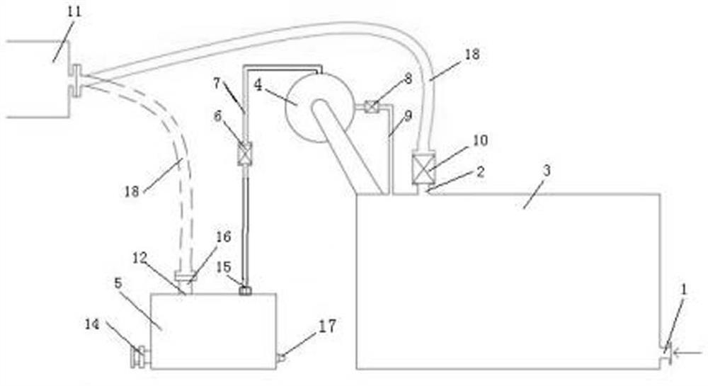
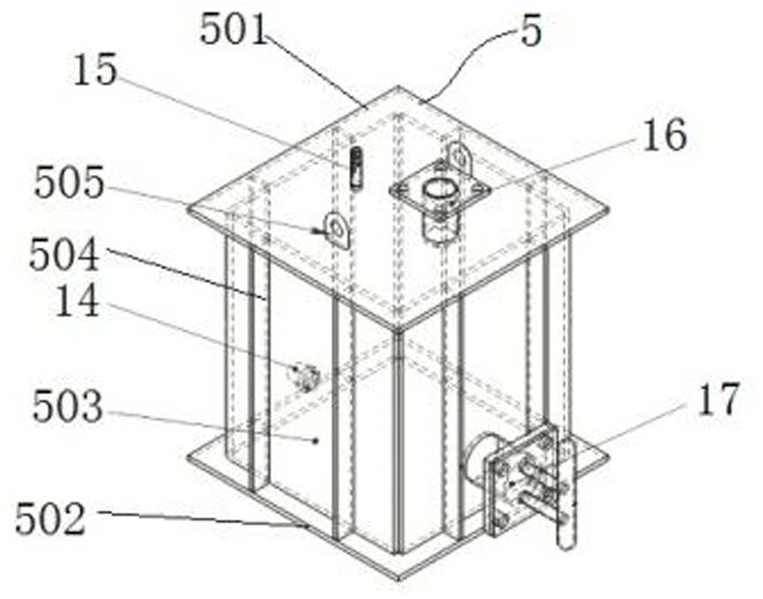
[0016] The vacuum oil filling structure of the large oil-immersed transformer and oil conservator of the present invention comprises a large oil-immersed transformer 3 having an oil inlet 1 and a first negative pressure port 2, and an oil conservator is arranged above the large oil-immersed transformer 3 4. The large oil-immersed transformer 3 is provided with a transitional oil tank 5 for vacuum oil filling, and a third communicating pipeline 7 with a third butterfly valve 6 is connected between the transitional oil tank 5 for vacuum oil filling and the oil conservator 4. The oil conservator 4 The second communication pipeline 9 with the second disc valve 8 is connected with the large oil-immersed transformer 3, the first negative pressure port 2 is provided wi...


PUM


Abstract

The invention relates to a vacuum oil injection structure of a large oil-immersed transformer and an oil conservator and a working method of the vacuum oil injection structure, the vacuum oil injection structure of the large oil-immersed transformer and the oil conservator comprises the large oil-immersed transformer with an oil inlet and a first negative pressure port, and the oil conservator isarranged above the large oil-immersed transformer; a vacuum oil injection transition oil tank is arranged beside the large oil-immersed transformer, a third communicating pipeline with a third butterfly valve is connected between the vacuum oil injection transition oil tank and the oil conservator, a second communicating pipeline with a second butterfly valve is connected between the oil conservator and the large oil-immersed transformer, and a first butterfly valve is arranged on the first negative pressure port. And a second negative pressure opening communicating with the vacuum pump is formed in the vacuum oil injection transition oil tank, an inlet of the vacuum pump is connected with the first end of the first connecting pipeline, and the second end of the first connecting pipeline is connected with the first butterfly valve or the second negative pressure opening. According to the invention, vacuum oil injection of transformer oil conservators of various types can be achieved ina matched mode. And sufficient degassing of the oil conservator and reasonable partial discharge of the transformer are ensured.

Description

Technical field: [0001] The invention relates to a vacuum oil filling structure of a large oil-immersed transformer and an oil conservator and a working method thereof. Background technique: [0002] In the vacuum oil filling process of traditional large oil-immersed transformers, only the oil tank part of the transformer can be vacuum oil filled, but the oil conservator part cannot be vacuum oil filled, resulting in insufficient degassing of the transformer oil in the oil conservator part. Make the partial discharge of the whole transformer too high. Invention content: [0003] In view of the deficiencies in the prior art, the technical problem to be solved by the present invention is to provide a vacuum oil filling structure of a large oil-immersed transformer and an oil conservator and a working method thereof. The design is reasonable, which is conducive to the vacuum oil filling of large oil-immersed transformers and oil conservator, to ensure the full degassing of t...

Claims


Application Information

Patent Timeline
Patent Type & Authority Applications(China)
IPC IPC(8): H01F27/14
CPCH01F27/14
Inventor 袁思议
Owner FUZHOU TIANYU ELECTRIC
Why Eureka
Try Eureka