Honeycombed ceramic slurry water cooling vacuum refiner

A technology of ceramic mud and water cooling, which is applied in the field of ceramic mud, can solve the problems of large upper shaft resistance and large power consumption, and achieve the effects of reasonable layout, automation, and uniformity

Inactive Publication Date: 2011-10-05
NANJING KERUI SPECIAL CERAMICS +1
View PDF9 Cites 0 Cited by
  • Summary
  • Abstract
  • Description
  • Claims
  • Application Information

AI Technical Summary

Problems solved by technology

[0010] CN2726850 discloses a split conical mud delivery tube for a vacuum mud mill, which overcomes the defects of large upper shaft resistance and large power consumption caused by the split conical mud delivery tube with transverse annular reinforcing ribs. The split conical mud conveying cylinder of the new vacuum mud refining machine is installed between the mud groove of the upper shaft of the vacuum mud refining machine and the vacuum chamber. The split conical mud conveying cylinder is a cone composed of 8 longitudinally evenly distributed guide ribs. shaped structure

Method used


Image

  • Honeycombed ceramic slurry water cooling vacuum refiner
  • Honeycombed ceramic slurry water cooling vacuum refiner
  • Honeycombed ceramic slurry water cooling vacuum refiner

Examples


Embodiment Construction

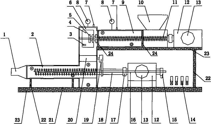
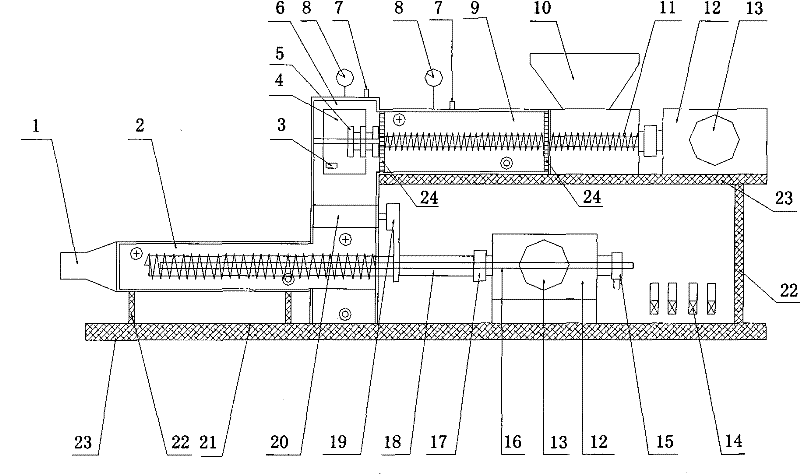
[0030] figure 1 In the schematic diagram of the honeycomb ceramic mud water cooling vacuum refining machine, the area within the double line is the cooling and vacuum area, ◎ is cooling water outlet, ◎ is cooling water inlet.

[0031] 1 mud outlet, 2 mud outlet, 3 photoelectric control device, 4 vacuum chamber window, 5 scraper, 6 vacuum chamber, 7 suction port, 8 vacuum gauge, 9 mud inlet, 10 feed port, 11 double agitator Mud shaft, 12 reducer, 13 frequency conversion motor, 14 control valve and flow meter, 15 cooling water inlet and outlet device, 16 shaft water inlet pipe, 17 coupling, 18 extrusion shaft, 19 transmission device, 20 double kneading rollers, 21 slides, 22 supports, 23 bases, 24 fences

[0032] ] Firstly, the overall design scheme is put forward according to the performance index, mechanical and electrical components, processing capacity, and finished product quality requirements of the honeycomb ceramic slurry water-cooled vacuum refining machine.

[0033...


PUM

PropertyMeasurementUnit
diameteraaaaaaaaaa
lengthaaaaaaaaaa

Abstract

The invention provides a honeycombed ceramic slurry water cooling vacuum refiner, comprising a slurry feed cylinder, slurry stirring shafts with helical blades, a vacuum chamber, a pumping hole, two kneading rollers, a photoelectric control device, a transmission mechanism, a hollow extruding shaft with helical blades, a slurry discharge cylinder, a fence which has section area close to and slightly smaller than the slurry feed cylinder, a cooling water device, a frame, a speed reducer and a variable-frequency motor, wherein the front end of the slurry stirring shafts with helical blades is provided with a slurry scraping knife. The slurry feed cylinder consists of two cylinders which are communicated, the section plane of the slurry feed cylinder is in a shape of a lying 8, and is communicated in the middle; the outlet end of the slurry feed cylinder is provided with the fence and the pumping port to form primary vacuum area; one slurry stirring shaft with the helical blade extends into each single cylinder, and is supported by a bearing with a seal ring; a bearing at the front end of the slurry stirring shaft is provided with a plurality of slurry scraping knives consisting of crossed blades; the fence is arranged at the outlet of the slurry feed cylinder; the upper end of the vacuum chamber is provided with the pumping port to ensure the vacuum chamber and the slurry discharge cylinder to form a secondary vacuum area; the lower part of the vacuum chamber is provided with two kneading rollers which are engaged with each other; the slurry outlet on the front part of the slurry discharge cylinder is a cone with narrowing opening.

Description

technical field [0001] The invention relates to a water-cooled vacuum kneading machine for ceramic mud, especially honeycomb ceramic mud. Background technique [0002] Honeycomb ceramics is a kind of porous ceramics. Due to its high specific surface area and high porosity, it is widely used as a three-way catalyst carrier for automobile exhaust purification and as a regenerator for preheating and recovery of metallurgical industrial waste gas. The thermal stability, compressive strength and other physical and chemical properties of honeycomb ceramics affect its use function, and its physical and chemical properties are directly related to raw materials and processing technology. The kneading after kneading of honeycomb ceramic raw materials is an important part of the processing technology, that is, kneading under vacuum conditions can further improve the uniformity and compactness of each component. In order to eliminate the heat generated by mechanical stirring, it is nec...

Claims


Application Information

Patent Timeline
Patent Type & Authority Patents(China)
IPC IPC(8): B28B3/22B28C1/16
Inventor 孔秋明孔德双谷昌军孔贵荣孔令仁
Owner NANJING KERUI SPECIAL CERAMICS
Why Eureka
Try Eureka