
Ceramic dielectric waveguide filter with transmission zero point

A waveguide filter and transmission zero-point technology, applied in the field of filters, can solve the problems of difficult metallization, difficult to realize, and difficult to process the transmission zero-point structure, so as to achieve the effect of simple processing and improved production efficiency

Pending Publication Date: 2020-12-11
浙江旦迪通信科技有限公司
View PDF0 Cites 1 Cited by
  • Summary
  • Abstract
  • Description
  • Claims
  • Application Information

AI Technical Summary

Problems solved by technology

At present, the most commonly used structure to realize the transmission zero point is to open blind holes with different thicknesses on the ceramic dielectric body to realize capacitive or inductive coupling, but the disadvantage is that it is more difficult to process thinner blind holes and metallization inside the holes.
There are also literatures that open holes on the side of the filter and add metal probes between different resonant cavities to achieve zero-point loading, but this structure is currently difficult to achieve
[0003] In summary, the transmission zero point structure of ceramic dielectric waveguide filters is difficult to process, which affects the production efficiency of ceramic dielectric waveguide filters

Method used


Image

  • Ceramic dielectric waveguide filter with transmission zero point
  • Ceramic dielectric waveguide filter with transmission zero point
  • Ceramic dielectric waveguide filter with transmission zero point

Examples


Embodiment Construction

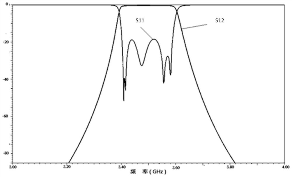
[0032] The present invention will be further described in detail below in conjunction with the accompanying drawings and embodiments. It should be understood that the specific embodiments described here are only used to explain the present invention, but not to limit the present invention. In addition, it should be noted that, for the convenience of description, only some structures related to the present invention are shown in the drawings but not all structures.

[0033] Ceramic dielectric waveguide filter is a filter designed and manufactured by utilizing the characteristics of low loss, high dielectric constant, frequency temperature coefficient and thermal expansion coefficient of dielectric ceramic materials, and can withstand high power. The ceramic dielectric waveguide filter is composed of several elongated resonators vertically multi-level series or parallel trapezoidal lines, and each resonator can also be called a resonant cavity. The ceramic dielectric waveguide ...


PUM


Abstract

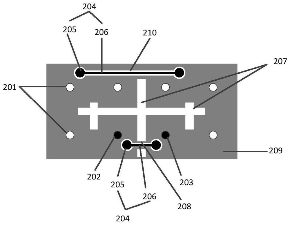
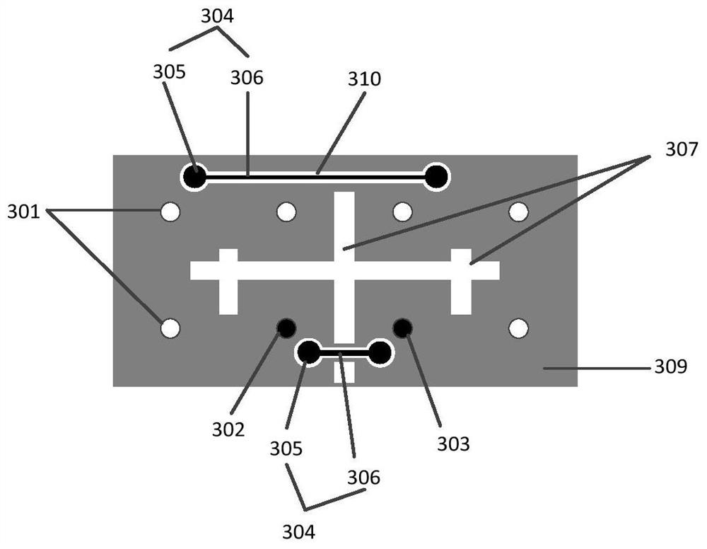
The invention discloses a ceramic dielectric waveguide filter with a transmission zero point. The filter comprises at least two resonant cavities, the sizes of the at least two resonant cavities are determined according to the transmission characteristics required by the filter, the input end and the output end of the filter are respectively located in the preset ranges of two different resonant cavities on the filter, at least one coupling structure is arranged on the surface of the filter, the coupling structure is arranged above the at least two resonant cavities, and each coupling structure comprises two metal coupling points respectively arranged in preset ranges of the two different resonant cavities and a metal wire for connecting the two metal coupling points. The provided ceramicdielectric waveguide filter with the transmission zero point is simple in structure, and the production efficiency of the ceramic dielectric waveguide filter can be improved.

Description

technical field [0001] Embodiments of the present invention relate to filter technology, in particular to a ceramic dielectric waveguide filter with transmission zero. Background technique [0002] Ceramic dielectric waveguide filters are more and more widely used in wireless communication equipment due to their compact size, low insertion loss and high power capacity. Ceramic dielectric waveguide filters often need to set at least one transmission zero point in the low-end frequency band and high-end frequency band of the working passband to improve the near-end rejection performance. The out-of-band rejection performance of the filter can also be improved by increasing the number of resonant cavities of the filter, but the increase in the number of resonant cavities will increase the volume of the filter. At present, the most commonly used structure to realize transmission zero point is to open blind holes with different thicknesses on the ceramic dielectric body to reali...

Claims


Application Information

Patent Timeline
IPC IPC(8): H01P1/20H01P1/208
CPCH01P1/2002H01P1/208
Inventor 李俊李晓辉
Owner 浙江旦迪通信科技有限公司
Learn More