Supercharge Your Innovation With Domain-Expert AI Agents!

Power supply cable stripping device

An electric cable and a matching technology, applied in the field of power supply cable stripping devices, can solve problems such as affecting construction progress, reducing construction progress, increasing labor intensity, etc., and achieving convenient replacement or maintenance, convenient cutting processing, and improving construction efficiency. Effect

Active Publication Date: 2020-12-11
ZHANGQIU POWER SUPPLY CO OF STATE GRID SHANDONG ELECTRIC POWER CO +1
View PDF4 Cites 5 Cited by
  • Summary
  • Abstract
  • Description
  • Claims
  • Application Information

AI Technical Summary

Problems solved by technology

[0003] During cable erection and maintenance, it is necessary to peel the cables before connecting them. However, the existing stripping device does not have a knife-edge adjustment structure, and the user cannot adjust the incision depth of the stripping device according to the thickness of the cable sheath, which reduces the applicability of the stripping device. , so that the stripping device cannot perform stripping operations on cables with different thicknesses. The use of the equipment is not flexible enough. The traditional stripping device is affected by the different bending degrees of the cables during use, and it is prone to blockage and jamming, which seriously affects the construction progress. The traditional stripping device does not have The measuring device cannot peel the cable according to the required length. Long stripping will affect the appearance of the cable connection. If the stripping is short, the two cables cannot be completely connected together, which will affect the later normal production use. It is not easy to pull out, which brings some inconvenience to the user, greatly increases the labor intensity and reduces the construction progress

Method used


Image

  • Power supply cable stripping device
  • Power supply cable stripping device
  • Power supply cable stripping device

Examples


Embodiment Construction

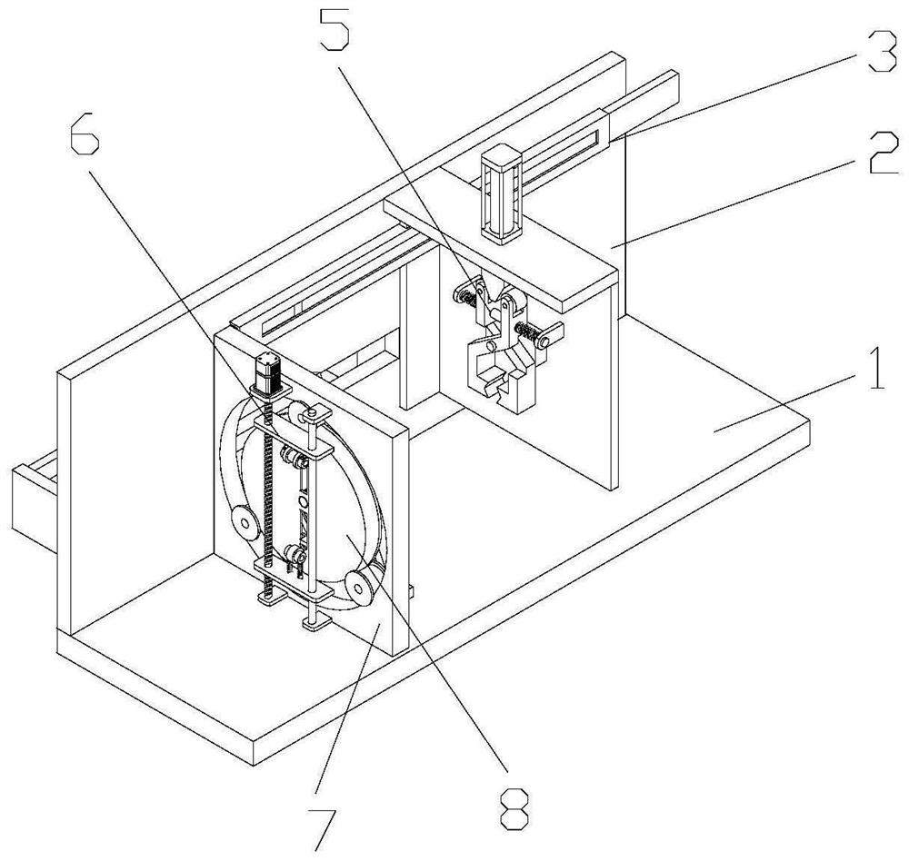
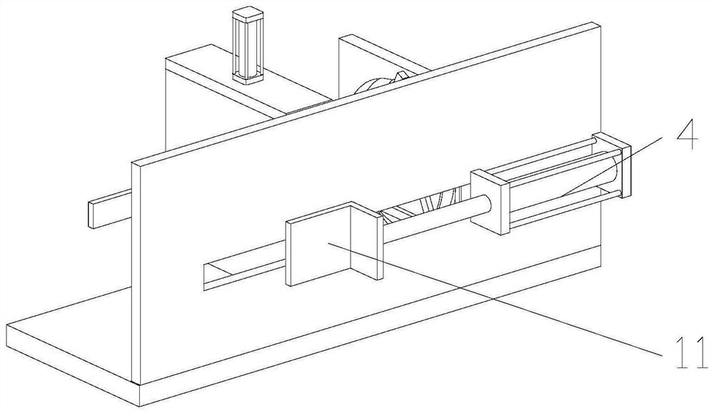
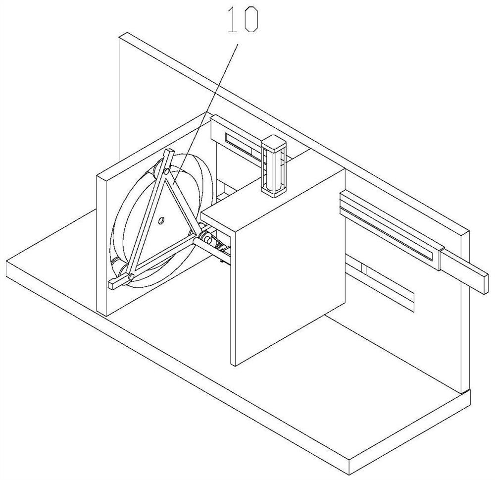
[0033] Attached below Figure 1-8 , clearly and completely describe the technical solutions in the embodiments of the present invention, obviously, the described embodiments are only some of the embodiments of the present invention, not all of them. Based on the embodiments of the present invention, all other embodiments obtained by persons of ordinary skill in the art without making creative efforts belong to the protection scope of the present invention.

[0034] In describing the present invention, it should be understood that the terms "longitudinal", "transverse", "upper", "lower", "front", "rear", "left", "right", "vertical", The orientations or positional relationships indicated by "horizontal", "top", "bottom", "inner", "outer", etc. are based on the orientations or positional relationships shown in the drawings, and are only for the convenience of describing the present invention, rather than indicating or It should not be construed as limiting the invention by imply...


PUM


Abstract

The invention discloses a power supply cable stripping device which comprises a base and a vertical plate, the vertical plate is installed on one side of the base, a first air cylinder, a measuring mechanism and a fixing mechanism are installed on the vertical plate, a connecting block is installed on a piston rod on the first air cylinder, and the connecting block is connected with the fixing mechanism. The measuring mechanism is matched with the fixing mechanism, and a supporting plate is installed on the base. The adjusting mechanism can adjust the position of the cutting blade, it is guaranteed that cables with different thicknesses can be peeled, cables with insulating skins with different thicknesses can be cut, the practicability of the device is greatly improved, the device can achieve the rotary cutting effect during cutting, and the cut insulating skins can be cut off. The cut insulating skin can be taken down conveniently, the measuring device is arranged to measure the cutcable, accurate cutting is achieved, stripping efficiency is guaranteed, and construction efficiency is improved.

Description

technical field [0001] The invention belongs to the technical field of cable stripping, in particular to a power supply cable stripping device. Background technique [0002] The cable wire is usually a rope-like cable twisted by several or several groups of wires [at least two in each group]. Each group of wires is insulated from each other and is often twisted around a center. Highly insulating covering, wire and cable refers to materials used for power, communication and related transmission purposes. There is no strict boundary between "wire" and "cable". Usually, products with few cores, small product diameter and simple structure are called wires, those without insulation are called bare wires, and others are called cables; Small ones (less than or equal to 6 square millimeters) are called small wires, and insulated wires are also called cloth wires. [0003] During cable erection and maintenance, it is necessary to peel the cables before connecting them. However, th...

Claims


Application Information

Patent Timeline
IPC IPC(8): H02G1/12
CPCH02G1/1265
Inventor 李延海高成高梓浩郝文杰李毅李烨韩万鹏李岩张文李青春张俊磊王婕
Owner ZHANGQIU POWER SUPPLY CO OF STATE GRID SHANDONG ELECTRIC POWER CO
Features
  • R&D
  • Intellectual Property
  • Life Sciences
  • Materials
  • Tech Scout
  • Unparalleled Data Quality
  • Higher Quality Content
  • 60% Fewer Hallucinations
Learn More