Embedded-permanent magnet reluctance type hybrid magnetic pole type memory motor

A memory motor and mixed magnetic pole technology, applied to synchronous motors with stationary armature and rotating magnets, magnetic circuit shape/style/structure, magnetic circuit, etc., can solve the problem of accidental demagnetization of low coercivity permanent magnets Low moment density, accidental demagnetization of permanent magnets, etc., to achieve effective reluctance torque, improve stability, and reduce dosage

Active Publication Date: 2020-12-11
SOUTHEAST UNIV
View PDF10 Cites 3 Cited by
  • Summary
  • Abstract
  • Description
  • Claims
  • Application Information

AI Technical Summary

Problems solved by technology

However, in the high-speed field-weakening region, although the field-weakening d-axis current pulse can achieve a certain degree of field weakening, the armature field-weakening current is still required to further expand the speed regulation range, and this current component may cause accidental demagnetization of the permanent magnet.
In addition, in order to realize the anti-saliency characteristic, more q-axis magnetic barriers are used on the rotor, resulting in a complex structure, and the use of low-coercivity permanent magnets with relatively weak magnetic energy products will lead to a low torque density of the motor, Therefore, a hybrid magnetic pole memory motor using both high and low coercive force permanent magnets was proposed.
[0004] At present, hybrid permanent magnet memory motors are mainly divided into series magnetic circuit structure and parallel magnetic circuit structure. In the series magnetic circuit structure, the low-coercivity permanent magnet operating point is stable, but the relative magnetic adjustment range is relatively narrow, and the charge and demagnetization current is relatively large; The magnetic adjustment range is wider in the parallel magnetic circuit structure, but the armature reaction is easy to cause accidental demagnetization of the low coercivity permanent magnet

Method used


Image

  • Embedded-permanent magnet reluctance type hybrid magnetic pole type memory motor
  • Embedded-permanent magnet reluctance type hybrid magnetic pole type memory motor
  • Embedded-permanent magnet reluctance type hybrid magnetic pole type memory motor

Examples


Embodiment Construction

[0014] The present invention will be described in detail below in conjunction with the accompanying drawings and specific embodiments.

[0015] The synchronous reluctance motor has a multi-layer rotor magnetic barrier, which relies on the reluctance torque generated by the asymmetry of the rotor magnetic circuit to work. The concept of the synchronous reluctance motor is applied to the memory motor. On the one hand, the multi-layer d-axis magnetic barrier helps to improve The anti-demagnetization ability of LCF, on the other hand, can reduce the inductance ratio of d and q axes, that is, increase the salient pole ratio of the motor, which helps to improve the torque density of the motor.

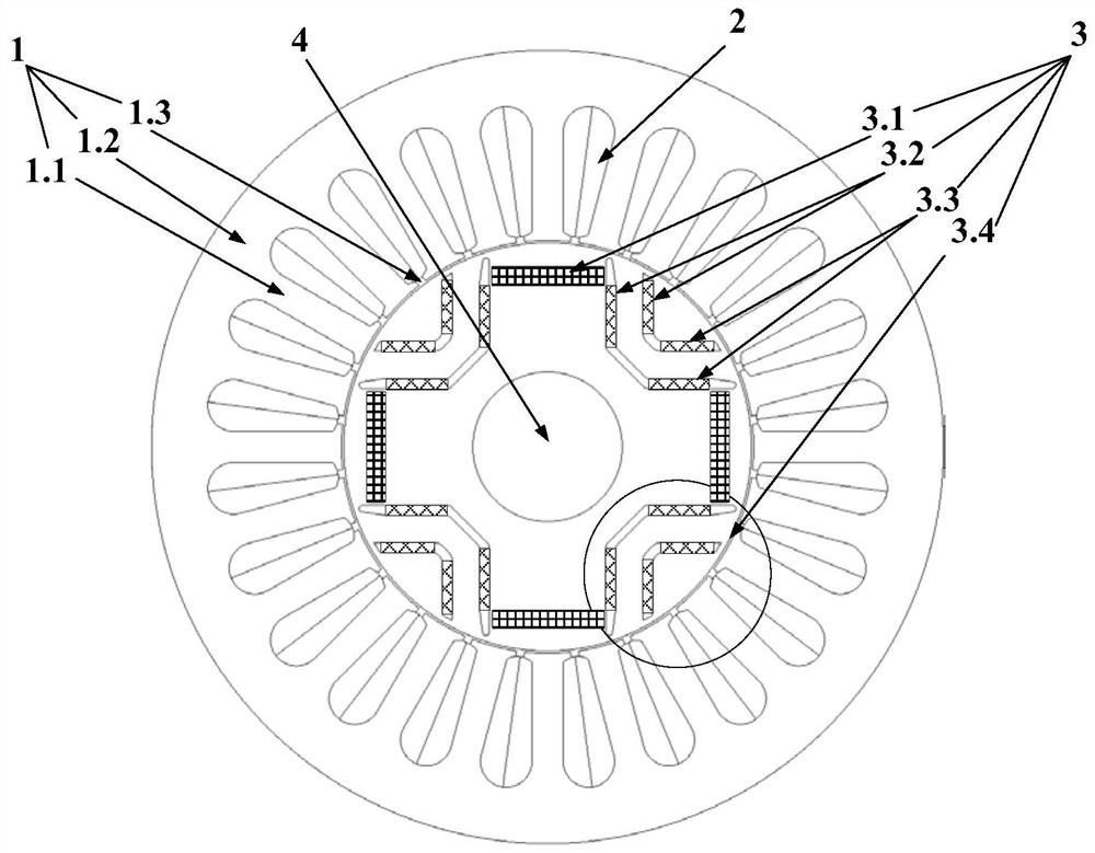
[0016] like figure 1 As shown, the embedded-permanent magnet reluctance hybrid magnetic pole memory motor involved in this example includes a stator 1 , an armature winding 2 , a hybrid permanent magnet rotor 3 and a rotating shaft 4 . The stator 1, the hybrid permanent magnet rotor 3 and t...


PUM


Abstract

The invention discloses an embedded-permanent magnet reluctance type mixed magnetic pole type memory motor which comprises a stator, an armature winding, a mixed permanent magnet rotor and a rotatingshaft, the armature winding is arranged on the stator, the stator, the mixed permanent magnet rotor and the rotating shaft are sequentially arranged from outside to inside, and a plurality of pairs ofmagnetic poles are arranged on a rotor core of the mixed permanent magnet rotor in the circumferential direction. an N pole is a first linear embedded radially-magnetized permanent magnet, a S pole is a permanent magnet auxiliary synchronous reluctance type, two pairs of tangentially-magnetized second and third permanent magnets are arranged at the S pole to form a double-layer V-shaped permanentmagnet auxiliary synchronous reluctance type structure, the first permanent magnet is placed by an air gap, and the bottom of the V-shaped permanent magnet structure is close to the rotating shaft. The coercive force of the first permanent magnet is smaller than that of the second and third permanent magnets. A large design space is obtained through mixed magnetic pole design so as to improve theoutput torque and reduce the torque pulsation, the series magnetic circuit structure can ensure the stability of the working points of the permanent magnets, and meanwhile, the use amount of the permanent magnets is reduced.

Description

technical field [0001] The invention relates to a memory motor, in particular to an embedded-permanent magnet reluctance type hybrid magnetic pole type memory motor. Background technique [0002] The permanent magnet synchronous motor (Permanent Magnet Synchronous Machine, PMSM) uses a traditional rare earth permanent magnet material (such as NdFeB) with a high magnetic energy product, which has the advantages of high power / torque density and high efficiency, so it is widely used in Aerospace, ship propulsion, electric vehicles and many other high-end equipment fields. Due to the high coercive force characteristics of permanent magnet materials (such as NdFeB), the traditional permanent magnet synchronous motor keeps the air gap magnetic field in the motor basically constant, and the speed regulation range is very limited when it is operated as an electric motor, because of its weak magnetic field in the high speed area. Speed ​​regulation brings challenges. People usually...

Claims


Application Information

Patent Timeline
Patent Type & Authority Applications(China)
IPC IPC(8): H02K1/27H02K21/14
CPCH02K1/2766H02K21/145H02K2201/03
Inventor 阳辉王逸贤林鹤云
Owner SOUTHEAST UNIV
Why Eureka
Try Eureka