
Ceramic radiating fin convenient to install

A ceramic heat sink, ceramic technology, applied in the direction of modification through conduction heat transfer, cooling/ventilation/heating transformation, electrical components, etc., can solve the problem of reducing the heat dissipation effect, not being able to install and fix the ceramic heat sink, and not being able to quickly dissipate heat, etc. problem, to achieve efficient heat dissipation and cooling, easy installation and use, and increase the effect of contact area

Pending Publication Date: 2020-12-11
容泰半导体(江苏)有限公司
View PDF0 Cites 0 Cited by
  • Summary
  • Abstract
  • Description
  • Claims
  • Application Information

AI Technical Summary

Problems solved by technology

[0002] Ceramic heat sink is a heat sink made of ceramic material, which has the characteristics of high temperature resistance and corrosion resistance, so ceramic heat sink can be used in various high temperature and highly corrosive fluids for heat dissipation, and the heat dissipation effect is good under corrosive fluids. In terms of service life, ceramic heat sinks are several times or dozens of times longer than ceramic heat sinks under the same circumstances. Ceramic heat sinks have been widely used in metallurgy, refractory materials, building materials, chemicals, nonferrous metals and other industries, saving a lot of energy for enterprises. It has been widely used in large quantities to reduce production costs. With the gradual increase in the use of ceramic heat sinks, the existing ceramic heat sinks can no longer meet people's needs, so ceramic heat sinks that are more convenient to use are needed; in ceramic heat sinks When using and installing, it is not possible to quickly install and fix the ceramic heat sink, which is not convenient for the installation and use of the ceramic heat sink. The overall cooling effect

Method used


Image

  • Ceramic radiating fin convenient to install
  • Ceramic radiating fin convenient to install
  • Ceramic radiating fin convenient to install

Examples


Embodiment Construction

[0022] In order to make the technical means, creative features, goals and effects achieved by the present invention easy to understand, the present invention will be further described below in conjunction with specific embodiments.

[0023] In the description of the present invention, it should be noted that the terms "upper", "lower", "inner", "outer", "front end", "rear end", "both ends", "one end", "another end" The orientation or positional relationship indicated by etc. is based on the orientation or positional relationship shown in the drawings, and is only for the convenience of describing the present invention and simplifying the description, rather than indicating or implying that the referred device or element must have a specific orientation, use a specific Azimuth configuration and operation, therefore, should not be construed as limiting the invention. In addition, the terms "first" and "second" are used for descriptive purposes only, and should not be understood ...


PUM


Abstract

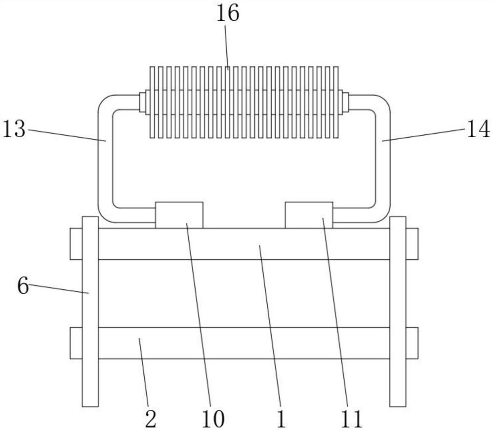
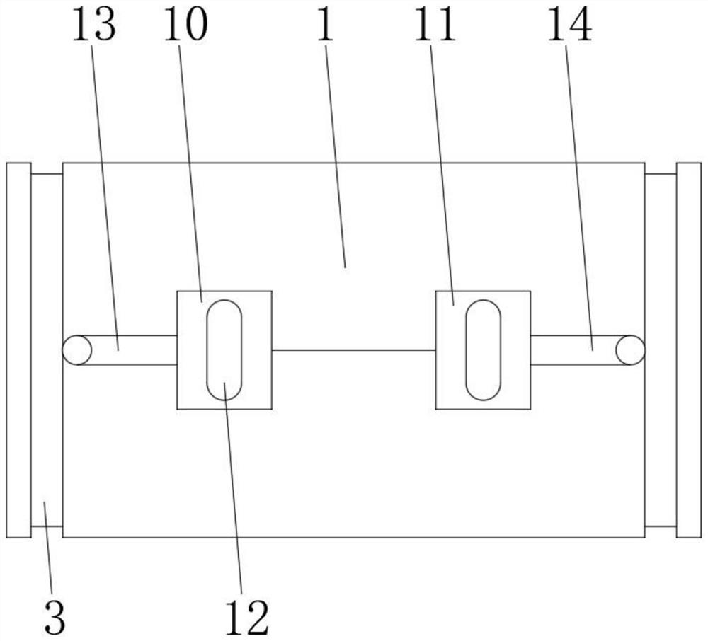
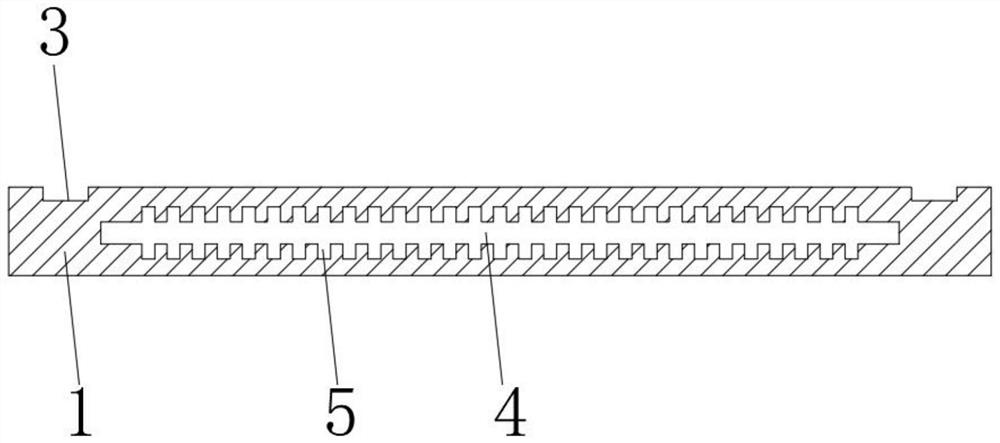
The invention discloses a ceramic cooling fin convenient to install. The ceramic cooling fin comprises a first ceramic patch and a second ceramic patch, wherein the first ceramic patch is located above the second ceramic patch, two frame fixing grooves are formed in the outer side of the first ceramic patch and the outer side of the second ceramic patch respectively, and heat conduction copper plates are fixedly mounted on the inner surfaces of the first ceramic patch and the second ceramic patch. The ceramic cooling fin convenient to install provided by the invention belongs to the field of ceramic cooling fins. The first ceramic patch and the second ceramic patch can be quickly clamped and fixed when the ceramic cooling fin is being installed, so installation and use of the ceramic cooling fin is facilitated; heat can be conducted to air cooling fins for cooling after the ceramic cooling fin makes contact with the heat; a structure that heat is absorbed through the first ceramic patch and the second ceramic patch and then heat is dissipated through the air heat dissipation fins is formed, the contact area of air is increased, and efficient heat dissipation and cooling are conducted.

Description

technical field [0001] The invention relates to the field of heat sinks, in particular to a ceramic heat sink that is easy to install. Background technique [0002] Ceramic heat sink is a heat sink made of ceramic material, which has the characteristics of high temperature resistance and corrosion resistance, so ceramic heat sink can be used in various high temperature and highly corrosive fluids for heat dissipation, and the heat dissipation effect is good under corrosive fluids. In terms of service life, ceramic heat sinks are several times or dozens of times longer than ceramic heat sinks under the same circumstances. Ceramic heat sinks have been widely used in metallurgy, refractory materials, building materials, chemicals, nonferrous metals and other industries, saving a lot of energy for enterprises. It has been widely used in large quantities to reduce production costs. With the gradual increase in the use of ceramic heat sinks, the existing ceramic heat sinks can no ...

Claims


Application Information

Patent Timeline
IPC IPC(8): H05K7/20
CPCH05K7/2039H05K7/20409H05K7/20509
Inventor 马春游
Owner 容泰半导体(江苏)有限公司
Learn More