
Automatic shearing device suitable for elevator balance compensation chain

A technology of balance compensation and shearing device, applied in shearing device, accessories of shearing machine, shearing machine equipment, etc., can solve the problem of inconvenient placement of elevator balance compensation chain shearing, inconvenient flow operation, and shearing knife damage Large and other problems, to achieve the effect of facilitating the streamlined operation, reducing the damage of the shearing knife, and reducing the labor intensity

Active Publication Date: 2020-12-15
JIANGSU XINGHUA RUBBER BELT
View PDF7 Cites 1 Cited by
  • Summary
  • Abstract
  • Description
  • Claims
  • Application Information

AI Technical Summary

Problems solved by technology

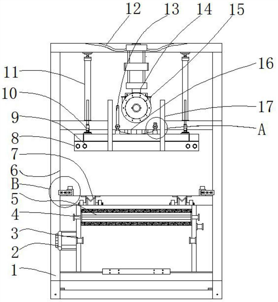
[0004] The purpose of the present invention is to provide a kind of automatic shearing device that is applicable to elevator balance compensation chain, to solve the automatic shearing device on the market that proposes in the above-mentioned background technology , Generally, manual cutting is adopted, first cutting the wrapping material, and then cutting with forceps, requiring workers to have strong labor, high labor intensity, excessive damage to the shearing knife, slow work efficiency, and more inconvenient for streamlined operations. The problem of inconvenient placement of elevator balance compensation chain shearing

Method used


Image

  • Automatic shearing device suitable for elevator balance compensation chain
  • Automatic shearing device suitable for elevator balance compensation chain
  • Automatic shearing device suitable for elevator balance compensation chain

Examples


Embodiment Construction

[0026] The following will clearly and completely describe the technical solutions in the embodiments of the present invention with reference to the accompanying drawings in the embodiments of the present invention. Obviously, the described embodiments are only some, not all, embodiments of the present invention. Based on the embodiments of the present invention, all other embodiments obtained by persons of ordinary skill in the art without making creative efforts belong to the protection scope of the present invention.

[0027] In the description of the present invention, unless otherwise stated, the meaning of "plurality" is two or more; the terms "upper", "lower", "left", "right", "inner", "outer" , "front end", "rear end", "head", "tail", etc. indicate the orientation or positional relationship based on the orientation or positional relationship shown in the drawings, and are only for the convenience of describing the present invention and simplifying the description, rather...


PUM


Abstract

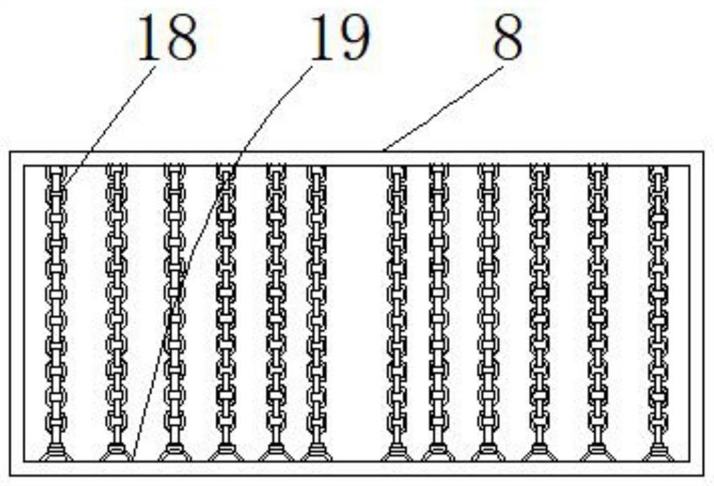
The invention relates to an automatic shearing device suitable for an elevator balance compensation chain. The automatic shearing device comprises a base, an infrared placing groove and combined plates, wherein a shell frame is arranged at the top end of the base; a motor is arranged on one side of the bottom end of the interior of the shell frame; a spindle is arranged on one side of the motor; connecting shaft barrels are arranged at the top end of the spindle; a compensation chain drum is arranged on the inner sides of the connecting shaft barrels; walking compensation chain frames are arranged at the top end of the compensation chain drum; a pressing cover plate is arranged above the walking compensation chain frames; connecting holes are arranged in the two sides of the interior of the pressing cover plate; and a protective frame is arranged at the top end of the pressing cover plate. The automatic shearing device has the beneficial effects that the lifting pressing cover plate iseffectively arranged between the walking compensation chain frames, so that a telescopic rod and a cutter head frame can conveniently shear the elevator balance compensation chain between the pressing cover plate and a compensation chain placing frame in a lifting manner, and the elevator balance compensation chain between the connecting shaft barrels can be placed between the pressing cover plate and the compensation chain placing frame for shearing.

Description

technical field [0001] The invention relates to the technical field of automatic shearing devices, in particular to an automatic shearing device suitable for elevator balance compensation chains. Background technique [0002] The elevator balance compensation chain needs to be cut to length during the production process. Because the elevator balance compensation chain skeleton uses electric welding anchor chain, the anchor chain is made of Q235 steel, which has high strength, and the polymer material on the outside also has high elasticity. Flexibility, the general cutting method is manual, and the wrapping material is cut first, which is inefficient. Therefore, it is necessary to improve the structure of the automatic shearing device of the elevator balance compensation chain. [0003] The automatic shearing device on the market generally adopts manual cutting, first cuts the wrapping material, and then cuts it with pliers. It is even more inconvenient for streamlined oper...

Claims


Application Information

Patent Timeline
Patent Type & Authority Applications(China)
IPC IPC(8): B23D31/00B23D33/00B02C1/00B02C1/14
CPCB23D31/00B23D33/00B02C1/14B02C1/005
Inventor 毛亮吴夕虎周朋根黄继来
Owner JIANGSU XINGHUA RUBBER BELT
Learn More