Magnetometer carrying device for aeromagnetic system of fixed-wing unmanned aerial vehicle

A technology of unmanned aerial vehicle and magnetometer, applied in the field of unmanned aerial vehicle, can solve the problems of low cost and low precision, and achieve the effect of easy height adjustment, easy disassembly and installation

Pending Publication Date: 2020-12-15
中国地质科学院地球物理地球化学勘查研究所
View PDF2 Cites 2 Cited by
  • Summary
  • Abstract
  • Description
  • Claims
  • Application Information

AI Technical Summary

Problems solved by technology

[0002] In recent years, with the continuous maturity of UAV technology, in view of its characteristics of less casualties, low cost, high efficiency, and the advantages of predictable high-precision data, low noise level, and high spatial resolution, UAV aeromagnetic The R&D and application of the UAV geophysical survey system have increasingly attracted the attention of various aviation geophysical companies in the world. The development of UAV aerial geophysical survey system has been started in the world since 2003, but it started relatively late in China. From 2008 to 2011, the 715 Institute of CSIC , the Institute of Remote Sensing and Digital Earth of the Chinese Academy of Sciences, the China Land and Resources Airborne Geophysical Prospecting and Remote Sensing Center, and Lawrey Industries have successively carried out research work based on fixed-wing UAV aeromagnetic measurement technology, and have achieved certain research results, but It has not been applied to actual measurement work. In 2012, Peking University and other units also carried out special research in this area, and obtained a certain amount of experimental data, but it has not been popularized and applied. The multi-rotor unmanned aerial vehicle developed by Judeng Exploration Company The machine is equipped with a fluxgate magnetometer system, which is light in weight but low in accuracy. In 2013, the Geophysical Research Institute broke through key technical problems such as UAV system modification and integration, and magnetic compensation, and successfully realized China's first domestically produced medium-sized fixed-wing UAV. The aeromagnetic measurement system fully considers the impact of aircraft modification on aerodynamics and how to obtain high-quality aeromagnetic data. With reference to the appearance of the time-domain avionics pod currently being developed by the Institute of Geophysical and Geochemical Exploration, this kind of probe cabin is designed. , such as the patent application number: CN201811628724.5, the application publication number is CN109709615A, and the name is a kind of airborne magnetic measurement system for rotor drones, including a cover, a central processing module, a casing and an optical pump magnetometer. An organic cover is installed at one end, and a circuit board is installed on one side of the inside of the casing through a first fixing bolt, a central processing module is installed at one end of one side of the circuit board, and a wireless signal transceiver module is installed at the other end of one side of the circuit board , the top of the casing is equipped with an optical pump magnetometer, and one side of the optical pump magnetometer is provided with a display screen, and one end of the top of the optical pump magnetometer is equipped with a solar panel through a carrier frame, and the solar panel is below A storage battery is installed inside the carrier frame, but the disassembly and installation of this patent are too complicated for use, and it is inconvenient to operate, and this patent cannot be adjusted in length, so it is inconvenient to use, and when the magnetic probe needs to be fixed, It cannot be adjusted according to the width of the magnetic probe, and it is not convenient to adjust the angle, and the existing level adjustment device needs to be manually completed by the staff, so it is difficult to adjust

Method used


Image

  • Magnetometer carrying device for aeromagnetic system of fixed-wing unmanned aerial vehicle
  • Magnetometer carrying device for aeromagnetic system of fixed-wing unmanned aerial vehicle
  • Magnetometer carrying device for aeromagnetic system of fixed-wing unmanned aerial vehicle

Examples


Embodiment 1

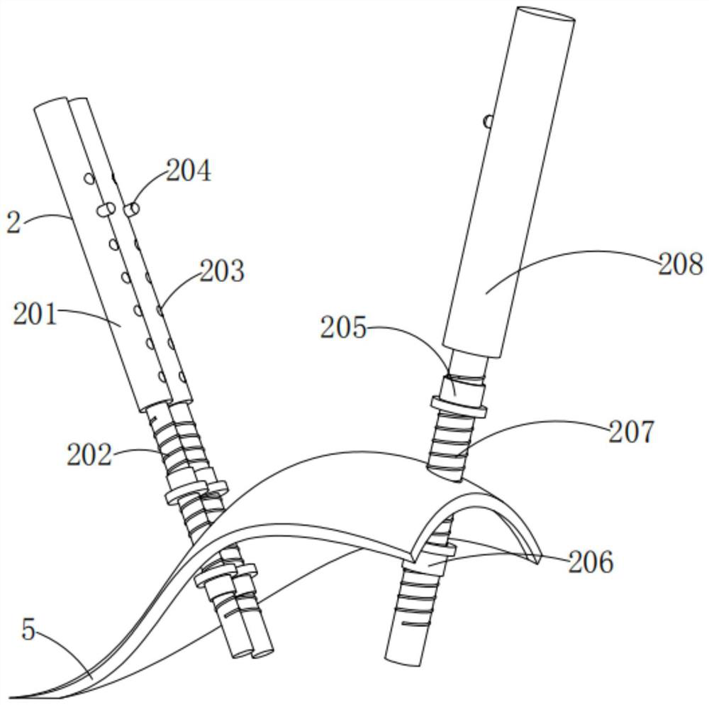
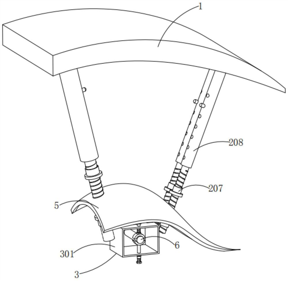
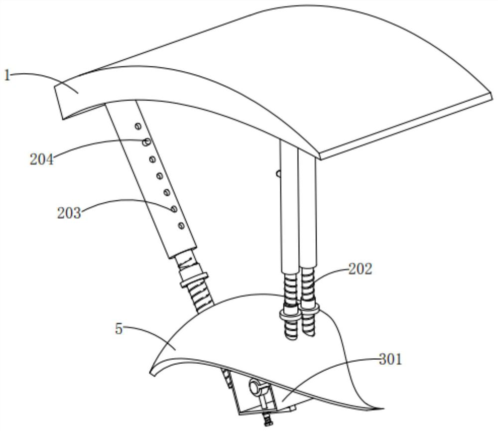
[0032] Example 1, such as figure 1 , figure 2 , image 3 , Image 6 with Figure 10 As shown, the present invention provides a magnetometer carrying device for the aeromagnetic system of a fixed-wing unmanned aerial vehicle, comprising a wing 1, the bottom of the wing 1 is fixedly connected with a telescopic mechanism 2, and the bottom of the telescopic mechanism 2 is fixedly connected with a The probe casing 5, the bottom of the inner wall of the probe casing 5 is fixedly connected with the adjustment mechanism 4, the bottom of the adjustment mechanism 4 is fixedly connected with the fixing mechanism 3, the telescopic mechanism 2 includes two first brackets 201 and a second bracket 208, the two first brackets 201 is slidably embedded with a first sliding rod 202, and the inside of the second bracket 208 is slidably embedded with a second sliding rod 207. One side of the outer surface of the two first brackets 201 and the second bracket 208 is provided with a plurality of ...

Embodiment 2

[0034] Example 2, such as Figure 4 , Figure 5 , Figure 7 As shown, the fixing mechanism 3 includes a rectangular universal joint 301, the top of the outer surface of the rectangular universal joint 301 is threadedly connected with a threaded rod 302, the bottom of the outer surface of the threaded rod 302 is fixedly connected with a bearing 303, and the outer surface of the rectangular universal joint 301 is The bottom is slidably embedded with a rotating rod 306, and the outer surface of the rotating rod 306 near the bottom is threadedly connected with a third fixed sleeve 305, and the opposite side of the rotating rod 306 and the bearing 303 is fixedly connected with a clamping block 304, and the two clamping blocks 304 are opposite to each other. One side of the universal joint 301 is fixedly connected with a buffer pad, and the opposite side of the two buffer pads is movably embedded with a magnetic probe 6, and the top of the outer surface of the rectangular universal...

Embodiment 3

[0036] Example 3, such as Figure 4 , Figure 8 with Figure 9 As shown, the adjustment mechanism 4 includes a support rod 401 and a threaded connecting rod 402, the bottom of the supporting rod 401 is movably embedded with a movable rod, the two ends of the movable rod are fixedly connected with a second vertical plate 406, and the bottom of the threaded connecting rod 402 is fixed A movable circular sleeve 405 is connected, and a connecting rod 403 is movably embedded inside the movable circular sleeve 405. Both ends of the connecting rod 403 are fixedly connected with a first vertical plate 404, and the bottom of the rectangular universal joint 301 is fixedly connected with a horizontal air bubble 7 , the bottoms of the two first vertical plates 404 and the two second vertical plates 406 are fixedly connected to the top of the rectangular universal joint 301, the outer surface of the top of the threaded connecting rod 402 is threaded with a threaded sleeve, and the top of ...


PUM


Abstract

The invention provides a magnetometer carrying device for an aeromagnetic system of a fixed-wing unmanned aerial vehicle, and relates to the technical field of unmanned aerial vehicles. The magnetometer carrying device for the aeromagnetic system of the fixed-wing unmanned aerial vehicle comprises a wing, wherein a telescopic mechanism is fixedly connected to the bottom of the wing; the bottom ofthe telescopic mechanism is fixedly connected with a probe jacket; the bottom of the inner wall of the probe jacket is fixedly connected with an adjusting mechanism; the bottom of the adjusting mechanism is fixedly connected with a fixing mechanism; the telescopic mechanism comprises two first support frames and a second support frame; first slide rods are glidingly embedded in the two first support frames; and a second slide rod is glidingly embedded in the second support frame. According to the magnetometer carrying device for the aeromagnetic system of the fixed-wing unmanned aerial vehicle, through elasticity of reset springs, left movable push buttons are fixedly embedded in left fixed grooves; then, the second slide rod at the right side is adjusted to be fixed, so that the goal of conveniently adjusting the height is achieved; the second fixed sleeve at the bottom of the right side is fixedly attached and connected to the bottom of the right side of the probe jacket through screw threads formed on the outer surface of the second slide rod; and dismounting and mounting are convenient.

Description

technical field [0001] The invention relates to the technical field of unmanned aerial vehicles, in particular to a magnetometer carrying device for an aeromagnetic system of a fixed-wing unmanned aerial vehicle. Background technique [0002] In recent years, with the continuous maturity of UAV technology, in view of its characteristics of less casualties, low cost, high efficiency, and the advantages of predictable high-precision data, low noise level, and high spatial resolution, UAV aeromagnetic The R&D and application of the UAV geophysical survey system have increasingly attracted the attention of various aviation geophysical companies in the world. The development of UAV aerial geophysical survey system has been started in the world since 2003, but it started relatively late in China. From 2008 to 2011, the 715 Institute of CSIC , the Institute of Remote Sensing and Digital Earth of the Chinese Academy of Sciences, the China Land and Resources Airborne Geophysical Pros...

Claims


Application Information

Patent Timeline
Patent Type & Authority Applications(China)
IPC IPC(8): B64D47/00
CPCB64D47/00B64U10/25B64U2101/00
Inventor 西永在李军峰刘俊杰吴珊廖桂香李飞
Owner 中国地质科学院地球物理地球化学勘查研究所
Why Eureka
Try Eureka