Novel material sealed component analysis device
A technology for composition analysis and new materials, applied in the direction of analysis by chemical reaction of materials, material analysis by observing the influence of chemical indicators, measurement devices, etc. equipment and other problems, to achieve the effect of strong strength, fast speed and fast crushing speed
- Summary
- Abstract
- Description
- Claims
- Application Information
AI Technical Summary
Problems solved by technology
Method used
Image

Examples
Embodiment 1
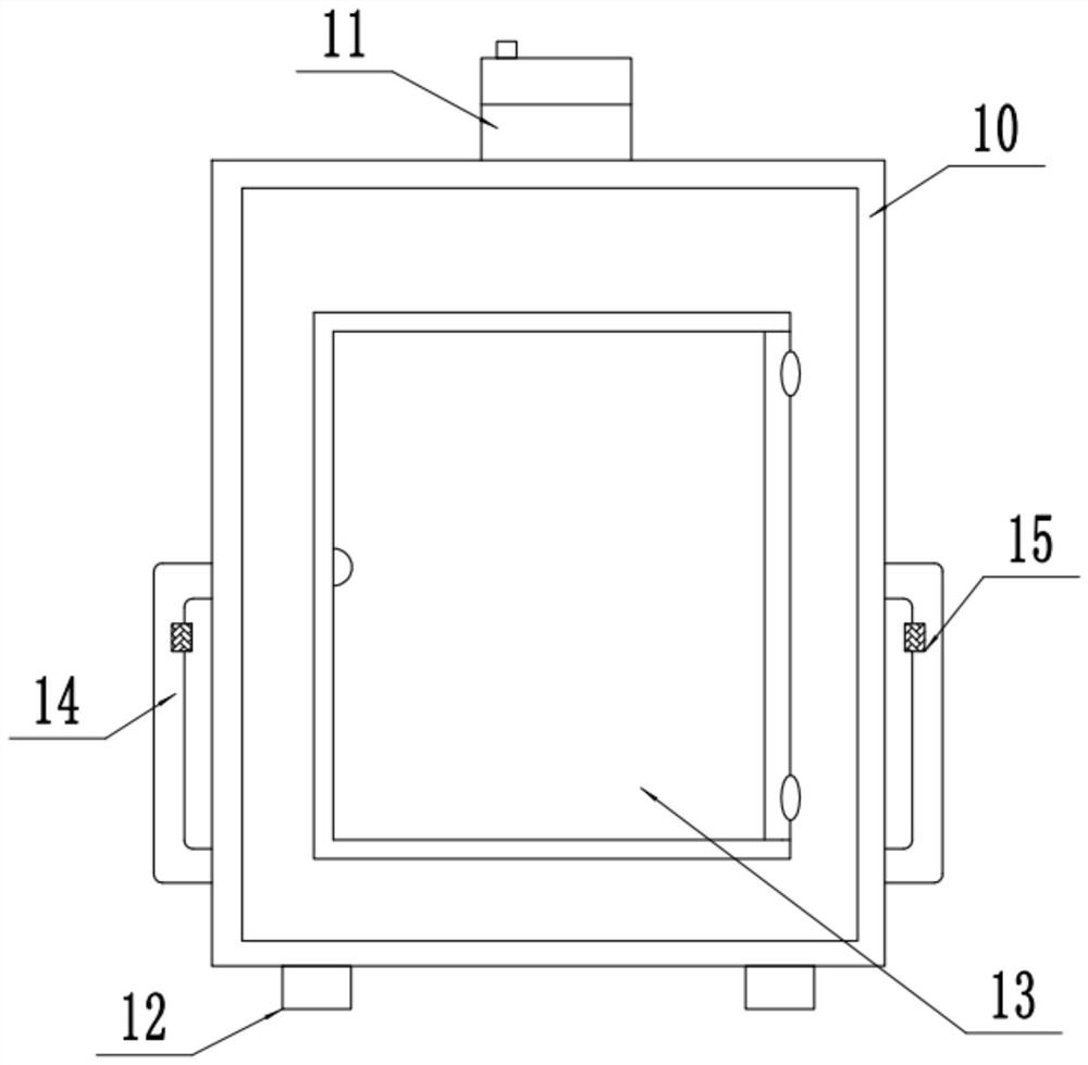
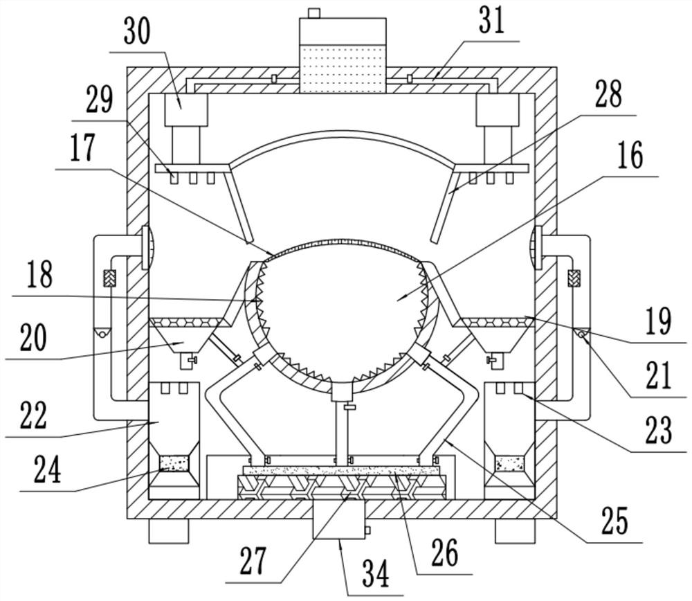
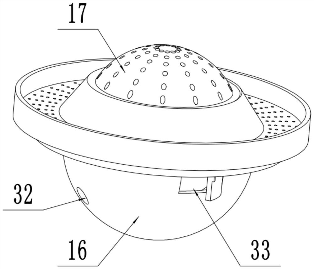
[0024] see Figure 1-3 , a new material sealed component analysis device, including an analysis box 10, a transparent box door 13, and an airflow crushing chamber 16; The middle part is hinged to be convenient to transparent box door 13, and the setting of transparent box door 13 is convenient to analyze the composition analysis situation of box body 10 inside while being convenient to analyze box body 10 interior new material. A group of airflow pulverization chambers 16 with a spherical structure are fixedly installed in the middle of the analysis box 10 . The top of the airflow pulverization chamber 16 is provided with an opening and a group of arc-shaped filter screens 17 protruding upwards in the middle are fixedly installed. The middle part of the front side of the jet milling chamber 16 is outwardly provided with a group of feeding ports 33 for inputting new materials to be pulverized. In the middle left of the bottom of the jet milling chamber 16, there are three group...
Embodiment 2
[0029] On the basis of Embodiment 1, the upper side of the high-pressure gas flow pipeline 25 is communicated with a branch pipe, and the end of the branch pipe is connected to the bottom of the decomposition detection tank 19. When the liquid reacts with each other, by controlling the size of the airflow input into the decomposition detection cell 19, the sufficient reaction between the new material in the decomposition detection cell 19 and the decomposition liquid is promoted, thereby improving the subsequent analysis accuracy.
[0030] The working principle of the present invention is: when in use, the new material to be analyzed is placed in the inside of the airflow crushing chamber 16 through the feed port 33, then the feed port 33 is closed, and then the gas compressor 27 is started to remove the nitrogen gas in the nitrogen chamber 34. Nitrogen is pressurized, and then flows out at high speed into the airflow crushing chamber 16 through the high-pressure airflow pipeli...
PUM
 Abstract
Description
Claims
Application Information
PatSnap Eureka turns technology decisions into work you can execute. Powered by our Innovation Knowledge Graph, it runs expert workflows across engineering, life sciences, materials and intellectual property. Get your review-ready output in minutes.


