Magnetic tunnel junction test method and test system

A technology of magnetic tunnel junction and testing method, which is applied in the direction of magnetic performance measurement, measuring device, and magnetic variable measurement, which can solve the problems of expensive equipment, increased maintenance costs, and low yield rate, so as to save equipment purchase costs and maintenance Cost, test cost reduction, low cost effect

Pending Publication Date: 2020-12-15
THE CHINESE UNIV OF HONG KONG SHENZHEN
View PDF0 Cites 0 Cited by
  • Summary
  • Abstract
  • Description
  • Claims
  • Application Information

AI Technical Summary

Problems solved by technology

The yield rate and performance of the magnetic tunnel junction are mainly determined by the quality of the magnesium oxide layer. If the growth parameters of the magnesium oxide insulating layer are not optimized, the grown magnesium oxide will have many holes, which will lead to a very low yield rate.
Usually, an ultra-high vacuum magnetron sputtering instrument is used to prepare a magnetic tunnel junction. When purchasing a magnetron sputtering instrument, it is also necessary to purchase corresponding process parameters. Typical examples are Singulus in Germany and Applied Materials in the United States, but the equipment price extremely expensive
Moreover, the magnetron sputtering apparatus of companies such as Singulus in Germany is suitable for mass production, and the process parameters need to be kept stable. Adjusting the process parameters will affect the equipment and increase maintenance costs, which is not conducive to further improvement of the process parameters in actual production.
However, using ordinary magnetron sputtering equipment, although the cost is low, it requires a lot of experiments to find out the appropriate process parameters and maintain process stability, and the efficiency is low.

Method used


Image

  • Magnetic tunnel junction test method and test system
  • Magnetic tunnel junction test method and test system
  • Magnetic tunnel junction test method and test system

Examples


Embodiment Construction

[0033] In order to facilitate the understanding of the present invention, the following will describe the present invention more fully in combination with specific embodiments. Preferred embodiments of the invention are given in the detailed description. However, the present invention can be embodied in many different forms and is not limited to the embodiments described herein. On the contrary, these embodiments are provided to make the understanding of the disclosure of the present invention more thorough and comprehensive.

[0034] Unless otherwise defined, all technical and scientific terms used herein have the same meaning as commonly understood by one of ordinary skill in the technical field of the invention. The terminology used herein in the description of the present invention is only for the purpose of describing specific embodiments, and is not intended to limit the present invention.

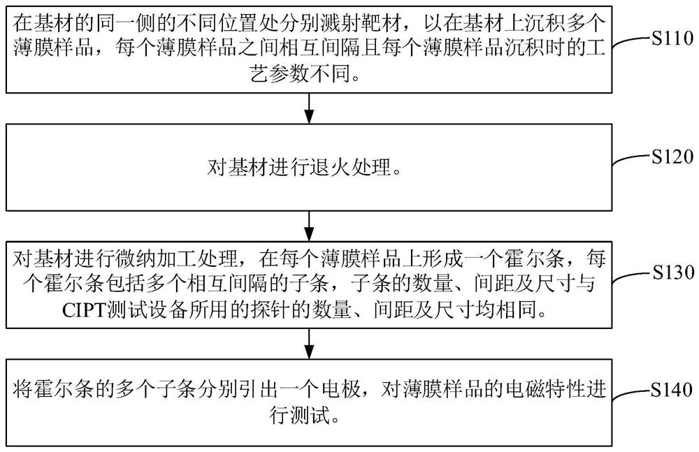
[0035] see figure 1 , the testing method of the magnetic tunnel junction of a...


PUM

PropertyMeasurementUnit
diameteraaaaaaaaaa
widthaaaaaaaaaa
thicknessaaaaaaaaaa

Abstract

The invention relates to a magnetic tunnel junction test method and test system. The test method comprises the following steps: sputtering a target material at different positions on the same side ofa base material so as to deposit a plurality of thin film samples on the base material, the thin film samples being spaced apart from each other and having different process parameters when the thin film samples are deposited; carrying out micro-nano processing treatment on the base material, and forming a Hall strip on each film sample, each Hall strip comprising a plurality of sub-strips which are arranged at intervals, and the number, spacing and size of the sub-strips being the same as the number, spacing and size of probes used by CIPT test equipment; and leading out one electrode from each sub-strip of the Hall strip and testing the electromagnetic property of each thin film sample. According to the magnetic tunnel junction test method, the efficiency is high, the cost is low, and the optimal process parameters for preparing the magnetic tunnel junction can be quickly and efficiently explored and obtained.

Description

technical field [0001] The invention relates to the field of magnetic tunnel junctions, in particular to a testing method and testing system for magnetic tunnel junctions. Background technique [0002] The magnetic tunnel junction refers to an extremely thin insulating layer sandwiched between two magnetic films, usually 1nm to 2nm thick magnesium oxide is used as the insulating layer. The magnetic tunnel junction is the basic storage unit of the magnetic random access memory and the core component of the hard disk head. It has a huge market in the information field. Only high-quality magnetic tunnel junctions can guarantee the preparation of high-performance devices. The yield rate and performance of the magnetic tunnel junction are mainly determined by the quality of the magnesium oxide layer. If the growth parameters of the magnesium oxide insulating layer are not optimized, the grown magnesium oxide will have many holes, resulting in a low yield rate. Usually, an ultra...

Claims


Application Information

Patent Timeline
Patent Type & Authority Applications(China)
IPC IPC(8): G01R33/12C23C14/54C23C14/35
CPCC23C14/35C23C14/54G01R33/1253
Inventor 赵月雷周艳
Owner THE CHINESE UNIV OF HONG KONG SHENZHEN
Why Eureka
Try Eureka