Antenna structure adopting worm and gear transmission unfolding

A technology of worm gear and antenna structure, which is applied to rotating antennas, antennas suitable for movable objects, antennas, etc., can solve the problems of low reliability, complex structure, large rotational load, etc., and achieve synchronization and stability Good, the transmission structure is compact, and the effect of ensuring the rotation accuracy

Active Publication Date: 2020-12-15
扬州船用电子仪器研究所
View PDF5 Cites 0 Cited by
  • Summary
  • Abstract
  • Description
  • Claims
  • Application Information

AI Technical Summary

Problems solved by technology

The torsion spring mechanism has the advantages of simple structure, small size, and light weight. However, for equipment with a large load, the torsion spring has insufficient torsion, low reliability, poor stability after deployment, and it is difficult to control the movement of the torsion spring mechanism in real time. , poor maneuverability
The gear mechanism has stable transmission and high reliability, but due to the small space of the missile-borne equipment, in order to improve the effective space of the equipment, the volume of the driving motor is severely limited, the output torque of the motor is small, and the rotational load of the equipment is large, so the gear mechanism A large transmission ratio is required, that is, multi-stage gears need to be designed to realize the rotation of the antenna
However, the gear mechanism with multi-stage transmission is complex in structure, has high design requirements, and takes up a lot of space; at the same time, the gear mechanism has no self-locking function, and it is difficult for the deployed antenna to maintain a stable state during high-speed flight, so the gear mechanism is not suitable for this missile. equipment

Method used


Image

  • Antenna structure adopting worm and gear transmission unfolding
  • Antenna structure adopting worm and gear transmission unfolding
  • Antenna structure adopting worm and gear transmission unfolding

Examples


Embodiment Construction

[0027] The present invention will be described in detail below with reference to the accompanying drawings and examples.

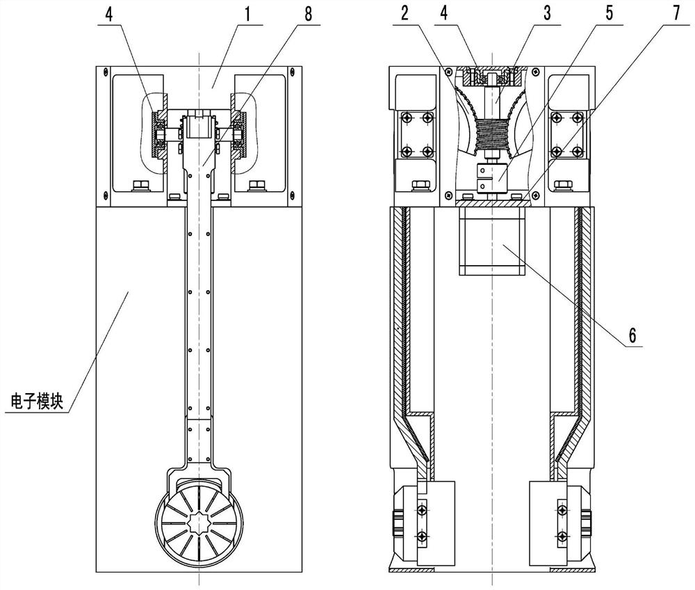
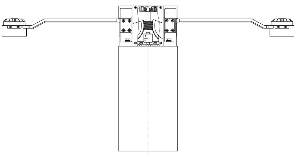
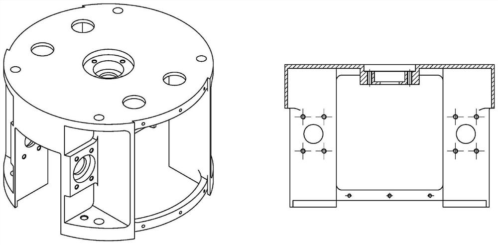
[0028] Such as figure 1 , figure 2 , Figure 6 As shown in the figure, an antenna structure deployed by worm gear transmission includes a mounting base 1, two worm gears 2 and a worm 3 fixed on the mounting base 1 through a bearing assembly 4, and are respectively arranged on the two worm gears 2 The antenna unit 8, the worm 3 is connected with the drive motor 6 through a coupling 5, the antenna unit 8 includes an antenna support rod 8-1 and an antenna 8-2, and one end of the antenna support rod 8-1 is fixed on the worm wheel 2, the other end is fixed to the antenna 8-2, and the antenna support rod 8-1 expands from a vertical state to a horizontal state with the movement of the worm gear 2, which is symmetrically arranged on both sides of the worm 3. In the present invention, the worm wheel 2, the worm 3 and the installation base 1 are fixed by the bea...


PUM


Abstract

The invention discloses an antenna structure adopting worm gear and worm transmission unfolding, which comprises a mounting base, two worm gears and a worm which are fixed on the mounting base througha bearing assembly, and antenna units respectively arranged on the two worm gears, the worm is connected with a driving motor through a coupling, each antenna unit comprises an antenna support rod and an antenna. One end of the antenna support rod is fixed on the worm wheel, the other end of the antenna support rod is fixed with the antenna, the antenna support rod is unfolded from a vertical state to a horizontal state along with the movement of the worm wheel and the worm, and the worm wheels are symmetrically arranged on two sides of the worm. The structure is large in transmission ratio,compact in structure, high in reliability, good in synchronism and stability and high in rotating precision.

Description

technical field [0001] The invention belongs to the technical field of structural design of missile-borne equipment, and specifically relates to an antenna structure deployed by worm gear transmission. Background technique [0002] With the development of science and technology and the improvement of military confrontation, the application fields of various guided weapon systems are constantly expanding, and missile-borne equipment has become a new research hotspot. For missile-borne equipment, its volume and weight are strictly limited, and the requirements for equipment reliability, environmental adaptability and vibration resistance are also very strict. [0003] A missile-borne device is mainly used for ballistic missile penetration missions. It is small in size and light in weight. It needs to realize simultaneous operation of multiple frequency bands and simultaneous work of sending and receiving in the same frequency band. It has 4 transmitting antennas and 2 receivin...

Claims


Application Information

Patent Timeline
Patent Type & Authority Applications(China)
IPC IPC(8): H01Q1/08H01Q1/12H01Q1/22H01Q1/28
CPCH01Q1/084H01Q1/1235H01Q1/22H01Q1/28
Inventor 杭磊刘则良窦长安
Owner 扬州船用电子仪器研究所
Why Eureka
Try Eureka