Power distribution cabinet for electric power engineering

A technology for power engineering and power distribution cabinets, applied in the substation/distribution device casing, electrical components, substation/switch layout details, etc., can solve problems such as being easily affected by the external environment, difficult to dissipate heat, hidden safety hazards, etc., to improve The effect of automatic control rate, reduction of energy output, and prevention of cold air leakage

Inactive Publication Date: 2020-12-15
储娟英
View PDF0 Cites 6 Cited by
  • Summary
  • Abstract
  • Description
  • Claims
  • Application Information

AI Technical Summary

Problems solved by technology

[0002] Power distribution cabinets are divided into power distribution cabinets, lighting distribution cabinets, and metering cabinets. They are the final equipment of the power distribution system. Power distribution cabinets are collectively referred to as motor control centers. , the motor control center is used in the occasions where the load is concentrated and there are many circuits. They distribute the electric energy of a certain circuit of the upper-level power distribution equipment to the nearby load. This level of equipment should provide protection, monitoring and control for the load. At present, the outdoor box The one-piece power distribution cabinet is usually a fully enclosed structure to prevent rain leakage and insects from crawling in. However, when the summer comes, due to the long-term operation of the power distribution cabinet equipment, the internal problems of the cabinet are too high and it is difficult to install Heat dissipation, which in turn leads to internal safety hazards, and at the same time has a great impact on the working environment of large internal parts and components, and even leads to fires. Among them, the traditional power distribution cabinet cooling equipment has a single function and is easily affected by external Influenced by the environment, when the overall external environment is hot, the heat dissipation effect is not ideal, and when the power distribution cabinet is high temperature, the rapid cooling effect is poor

Method used


Image

  • Power distribution cabinet for electric power engineering
  • Power distribution cabinet for electric power engineering
  • Power distribution cabinet for electric power engineering

Examples


Embodiment 1

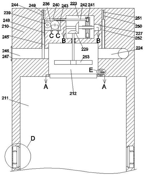
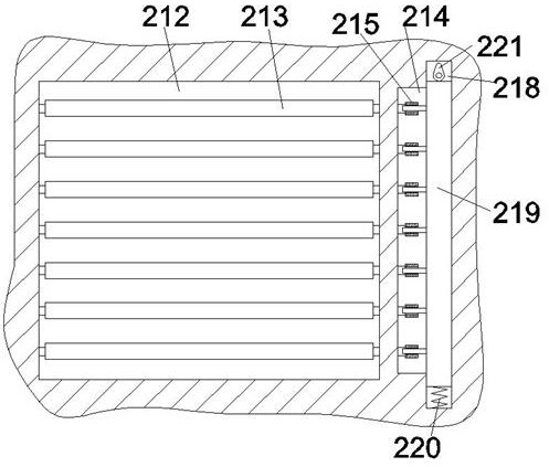
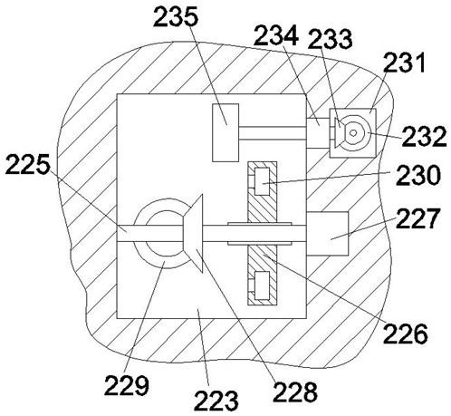
[0027] The cold air is directly supplied through the cold air channel 224, so that the cold air flows into the equipment inner cavity 211 through the air inlet cavity 212, and realizes rapid cooling in the equipment inner cavity 211, so that it is not affected by the external environment and achieves a rapid cooling effect. The second motor 227 drives the first rotating shaft 225 to rotate, and the first bevel gear 228 driven by the first rotating shaft 225 drives the second bevel gear 229 to rotate, wherein because the third gear 226 is far away from the fourth gear 235, at this time, the fourth gear 235 is in the non-working state, and then the second bevel gear 229 drives the fan blade 253 to rotate, so that the cold air is quickly sent into the equipment cavity 211, and the second motor 227 is controlled to stop rotating until the temperature of the equipment cavity 211 is lowered. The block 256 is pressed by the third spring 258 to automatically close the opening 254, ther...

Embodiment 2

[0029] When ordinary heat dissipation is required, the first motor 238 drives the second gear 237 to rotate, so that the second gear 237 drives the second rack 243 and the linkage slider 242 to slide to the left, and then the linkage slider 242 drives the third gear 226 is meshed with the fourth gear 235. At the same time, the first gear 239 is driven to rotate when the second rack 243 rotates. Since the rotation direction of the first gear 239 is opposite to that of the second rack 243, the second rack 243 is rotated. A gear 239 drives the first rack 248 and the second baffle plate 245 to overcome the top pressure of the second spring 249 to slide upwards, so that the bottom section of the second baffle plate 245 is away from the air inlet passage 246, so as to realize the opening of the air inlet passage 246, and at the same time , because the first baffle plate 252 is subjected to automatic gravity, the bottom section of the first baffle plate 252 extends into the cold air p...


PUM


Abstract

The invention discloses a power distribution cabinet for electric power engineering, which comprises a cabinet body, the cabinet body is internally provided with an equipment inner cavity, the top wall of the equipment inner cavity is internally provided with an air inlet inner cavity in a communicating manner, and the top wall of the air inlet inner cavity is connected with an air inlet fan bladein a running fit manner. The power distribution cabinet is characterized in that an air inlet channel communicating with the outside is formed in the left side wall of the air inlet inner cavity, a cold air channel communicates with the right side wall of the air inlet inner cavity, and the side, away from the air inlet inner cavity, of the cold air channel is connected with an external cold airsupply device. A plurality of sets of rotating blades arranged in a transverse extending mode are further connected into the air inlet inner cavity in a rotating fit mode, a first inner control cavityis further formed in the right side wall of the air inlet inner cavity, and a driving control mechanism used for controlling the air inlet fan blades and the rotating blades to work is arranged on the upper side of the air inlet inner cavity. Uni-directional air outlet mechanism are symmetrically arranged in the left side wall and the right side wall of the equipment inner cavity. The power distribution cabinet has the advantages that the automatic control can be realized, in addition, various heat radiation modes can be realized, and the cooling effect is improved.

Description

technical field [0001] The invention relates to the technical field of power distribution cabinets, in particular to a power distribution cabinet for power engineering. Background technique [0002] Power distribution cabinets are divided into power distribution cabinets, lighting distribution cabinets, and metering cabinets. They are the final equipment of the power distribution system. Power distribution cabinets are collectively referred to as motor control centers. , the motor control center is used in the occasions where the load is concentrated and there are many circuits. They distribute the electric energy of a certain circuit of the upper-level power distribution equipment to the nearby load. This level of equipment should provide protection, monitoring and control for the load. At present, the outdoor box The one-piece power distribution cabinet is usually a fully enclosed structure to prevent rain leakage and insects from crawling in. However, when the summer come...

Claims


Application Information

Patent Timeline
Patent Type & Authority Applications(China)
IPC IPC(8): H02B1/56H02B1/30
CPCH02B1/30H02B1/306H02B1/565
Inventor 储娟英
Owner 储娟英
Why Eureka
Try Eureka