Folding modular box-type slide rail photovoltaic module

A technology for photovoltaic modules and foldable modules, applied in photovoltaic modules, photovoltaic power generation, support structures of photovoltaic modules, etc., can solve the problems of large area and low space utilization, and achieve high light energy utilization, high space utilization, adaptable effect

Pending Publication Date: 2020-12-15
刘宗昊
View PDF2 Cites 2 Cited by
  • Summary
  • Abstract
  • Description
  • Claims
  • Application Information

AI Technical Summary

Problems solved by technology

However, in this scheme, the photovoltaic mechanism is deployed from both sides, and the area is still large after being folded, and the space utilization rate is low

Method used


Image

  • Folding modular box-type slide rail photovoltaic module
  • Folding modular box-type slide rail photovoltaic module
  • Folding modular box-type slide rail photovoltaic module

Examples


Embodiment 1

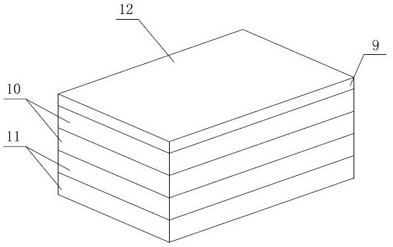
[0039] Such as Figure 10-11 As shown, a photovoltaic assembly of a folded and assembled box-type slide rail is composed of a central assembly 9, an outer box 10 and an inner box 11 to form a photovoltaic assembly, and the photovoltaic assembly is installed on a light-following platform 16 through a bracket 15; the light-following A photoelectric sensor connected to the photovoltaic module is provided on the platform 16, and a pitch direction stepper motor 18 for adjusting the pitch angle of the photovoltaic module and a horizontal direction stepper motor 19 for adjusting the horizontal angle of the photovoltaic module are provided on the bracket 15; The photoelectric sensor receives the illumination angle signal of the photovoltaic module, and then controls and adjusts the pitch angle and horizontal angle of the photovoltaic module through the control box 17 on the light tracking platform 16, so that the light tracking can be realized.

[0040] Such as Figure 1-2As shown, t...

Embodiment 2

[0042] On the basis of Embodiment 1, the outer boxes 10 are detachably connected. In this embodiment, a buckle structure can be adopted to facilitate disassembly and installation, and realize the addition and deletion of the outer box body 10 .

Embodiment 3

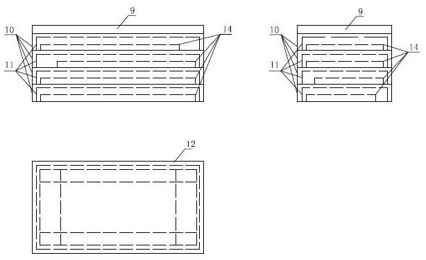
[0044] On the basis of Embodiment 1 or 2, each of the outer boxes 10 is provided with two inner boxes 11, and the positions of the slide rails in the upper and lower outer boxes 10 are perpendicular to each other, that is, they are located in the upper outer box. The inner box body 11 in the body 10 is perpendicular to the sliding direction of the inner box body 11 located in the lower outer box body 10; at the same time, the sliding directions of the two inner box bodies 11 in the same outer box body 10 are opposite, and the same outer box body 10 The sliding directions of the photovoltaic panels 3 14 in the two inner boxes 11 are opposite.

[0045] In order to improve the utilization rate of space, the present invention adopts the method of hierarchical folding and unfolding, and its gradual unfolding steps are as follows:

[0046] 1. If image 3 As shown, when the first stage is deployed, the inner box body 11 protrudes outwards.

[0047] 2. After the first-level expansio...


PUM


Abstract

The invention discloses a folding modular box-type slide rail photovoltaic module, which comprises a plurality of outer box bodies installed in an overlapping manner, a central assembly is arranged atthe upper end of each outer box body, and an inner box body is arranged in each outer box body; the central assembly is installed on the upper portion of the outer box body through a buckle, and a first photovoltaic panel is fixedly installed on the upper portion of the central assembly. The inner box body is installed in the outer box body through a sliding rail, and the inner box body slides tothe exterior of the outer box body or slides into the outer box body along the sliding rail. A second photovoltaic panel is fixedly installed on the upper surface of the inner box body, and a third photovoltaic panel is installed in the inner box body through a sliding rail. The module is formed by assembling the central assembly, the outer box body and the inner box body, can be increased or decreased according to the electricity consumption and the available area, is convenient to mount and dismount, and can be dismounted without tools. Meanwhile, the photovoltaic assembly box is suitable for most types of common photovoltaic assemblies on the market, only the box body with the corresponding size needs to be selected according to the size of the photovoltaic panel, and the flexibility is very high.

Description

technical field [0001] The invention relates to the technical field of folding and unfolding equipment for photovoltaic mechanisms, in particular, to a photovoltaic module of folding and modularized box-type slide rails that can fully improve space utilization. Background technique [0002] Most of the existing photovoltaic modules have a large area and are placed outdoors for a long time. The surface is easily covered by dust, snow and other urban pollutants, resulting in a decrease in power generation efficiency. Regular manual cleaning is required, which is inconvenient for maintenance and difficult to operate. Even in bad weather without sunlight, or even in extreme climates, it is still placed outdoors and suffers in vain from the natural wear and tear caused by the harsh environment, resulting in a short service life. Existing solar panel arrays cannot be stowed away, occupy a large area, and have a relatively large area exposed to wind. When fighting against extreme w...

Claims


Application Information

Patent Timeline
Patent Type & Authority Applications(China)
IPC IPC(8): H02S20/32H02S30/20H02S40/30F24S30/45
CPCF24S30/45H02S20/32H02S30/20H02S40/30Y02E10/47Y02E10/50
Inventor 刘宗昊
Owner 刘宗昊
Why Eureka
Try Eureka