A hairtail processing device

A processing device and technology for hairtail, which are applied in the directions of processing fish, cutting fish into components, separating solids, etc., can solve problems such as inability to cut hairtail in batches, and achieve the effects of improving convenience, saving processes, and reducing complexity.

Active Publication Date: 2022-01-18
聊城易海食品有限公司
View PDF9 Cites 0 Cited by
  • Summary
  • Abstract
  • Description
  • Claims
  • Application Information

AI Technical Summary

Problems solved by technology

[0002] For example, the publication number is a hairtail processing device with high efficiency for removing black lines and fins. Stopper, viscera remover, base and filter screen, fin stopper is movably connected on the top of the hairtail processing device, fish body stopper is movably connected under the fish fin stopper, and fish body stopper is movably connected There is a viscera remover, the base is fixedly connected to the bottom of the fish body limiter, and the filter screen is fixedly connected between the bases, and the part cut by the top of the cutting knife is bowl-shaped and semi-arc, with three pointed faces facing the hairtail black line and viscera For removal, the shape of the cutting surface is bowl-shaped and semi-arc, and the black line and internal organs are wrapped by the curved shape of the arc surface, so that it will not cause problems such as unclean removal. At the same time, there are grooves on the blade, There is an elliptical bump on the groove to limit the removed visceral black line, which is convenient for users to recycle and achieve better processing effect on hairtail; but this device cannot cut hairtail in batches

Method used


Image

  • A hairtail processing device
  • A hairtail processing device
  • A hairtail processing device

Examples


specific Embodiment approach 1

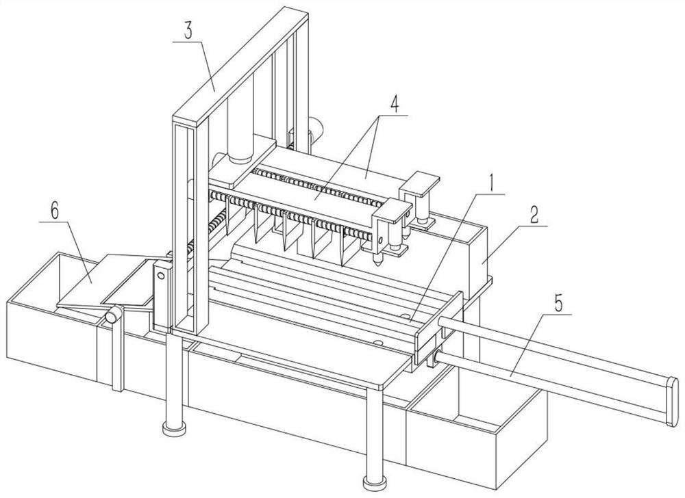
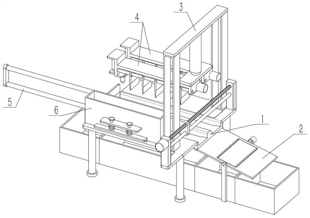
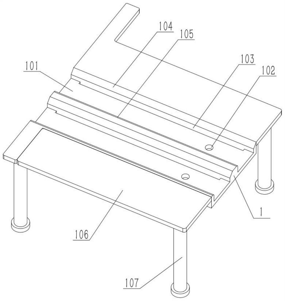
[0028] As shown in the figure, a hairtail processing device includes a processing table 1, a placement groove 101 and a positioning hole 102. The upper end of the processing table 1 is provided with a plurality of evenly distributed placement grooves 101 from front to back. Positioning holes 102 are provided, and the number of positioning holes 102 is the same as that of the placement slots 101 , and the plurality of positioning holes 102 are respectively located in the middle of the right side of the plurality of placement slots 101 . The width of placing groove 101 is close to the width of hairtail, and the length of placing groove 101 is longer than the length of hairtail. A hairtail is placed in each placement groove 101, and the head of the hairtail is located at the positioning hole 102, and the hairtail is positioned by inserting a rod-shaped member into the positioning hole 102, so that the hairtail is processed at a fixed point. The depth of placement groove 101 is cl...

specific Embodiment approach 2

[0029] As shown in the figure, the hairtail processing device also includes a laminating plate 106, a support portion 107, a heat preservation bin 2, a connecting portion 201, a screw I202, a round rod I203, a column 204 and a motor I205, and the front and rear ends of the processing table 1 are fixed. Connect a fitting plate 106, the lower end of each fitting plate 106 is all affixed to the support portion 107, the lower end surface of the heat preservation bin 2 is slidably fitted with the fitting plate 106, the connecting portion 201 is fixed on the left end of the heat preservation bin 2, and the connecting portion 201 is threaded. Connected to the lead screw I202, the connecting part 201 is slidably connected to the round rod I203, and there are two columns 204. On the two columns 204, the output shaft of the motor I205 is fixedly connected to one end of the lead screw I202, the motor I205 is fixedly connected to the column 204 at the corresponding position, and the two co...

specific Embodiment approach 3

[0030]As shown in the figure, the processing table 1 is provided with a reversed surface 104 and an arcuate surface 105 , and the inverted surface 104 and the arcuate surface 105 are respectively located at the edges of the upper end, the front end, and the front end of the placing groove 101 . The inverted surface 104 is convenient for the hairtail at the lowermost end of the thermal insulation storehouse 2 to be slightly inclined when passing the inverted surface 104, and then can be obliquely inserted into the placement groove 101, so as to prevent the fatter hairtail from accidentally skipping the placement groove 101. The arc surface 105 can make the hairtail at the lowermost end of the thermal insulation storehouse 2 be subjected to an oblique upward support force when passing through, so as to prevent two hairtails from being squeezed in a placement groove 101. Because the depth of the placement groove 101 is close to the thickness of a hairtail, the two hairtails squeeze...


PUM


Abstract

The present invention relates to fish processing, more specifically to a hairtail processing device. It includes a processing table, placement grooves and positioning holes. The upper end of the processing table is provided with a plurality of evenly distributed placement grooves from front to back. The processing table is provided with positioning holes. They are located in the middle of the right side of the multiple placement slots. The position where the fish tail can be dropped is closer to the left end of the processing table. Let the larger part of the hairtail body fall farther away from the processing table. Realize the classification of large and small segments, and realize the separation of high-quality products and inferior products. Then move the branch plate to the right, and start the electric push rod II. The electric push rod II drives the push plate to descend, and the push plate pushes the fish head from the positioning pin to fall back to the placement slot, so as to realize the return of the branch plate. The right side of the processing table saves the process. Fixed-point processing reduces the complexity of equipment adjustment and improves the convenience of equipment use.

Description

technical field [0001] The invention relates to fish processing, more specifically to a hairtail processing device. Background technique [0002] For example, the publication number is a hairtail processing device with high efficiency for removing black lines and fins. Stopper, viscera remover, base and filter screen, fin stopper is movably connected on the top of the hairtail processing device, fish body stopper is movably connected under the fish fin stopper, and fish body stopper is movably connected There is a viscera remover, the base is fixedly connected to the bottom of the fish body limiter, and the filter screen is fixedly connected between the bases, and the part cut by the top of the cutting knife is bowl-shaped and semi-arc, with three pointed faces facing the hairtail black line and viscera For removal, the shape of the cutting surface is bowl-shaped and semi-arc, and the black line and internal organs are wrapped by the curved shape of the arc surface, so that...

Claims


Application Information

Patent Timeline
Patent Type & Authority Patents(China)
IPC IPC(8): A22C25/14A22C25/08A22C25/18B07B13/08B08B9/093
CPCA22C25/142A22C25/18A22C25/08B08B9/093B07B13/08
Inventor 王亦婷
Owner 聊城易海食品有限公司
Why Eureka
Try Eureka