
A composite beam

A technology of composite beams and beams, applied in the field of composite beams, can solve problems such as unsatisfactory, shear resistance of shear-resistant connectors cannot be fully utilized, shear-resistant connection fractures, etc.

Inactive Publication Date: 2003-09-10
BHP STEEL PTY LTD
View PDF1 Cites 0 Cited by
  • Summary
  • Abstract
  • Description
  • Claims
  • Application Information

AI Technical Summary

Problems solved by technology

[0019] It was also found that as little as 1 mm of longitudinal slippage between the concrete slab and the steel beam would result in a sudden failure of the shear-resistant connection, which is totally unsatisfactory since such failure is difficult to overcome by design, and Obviously, the shear resistance of such shear connectors cannot be fully utilized.
[0020] In addition, it was found that conventional transverse reinforcement, which in the past was thought to prevent premature longitudinal shear failure, appeared to promote transverse cracking and was therefore entirely unsatisfactory from this point of view

Method used


Image

  • A composite beam
  • A composite beam
  • A composite beam

Examples


Embodiment Construction

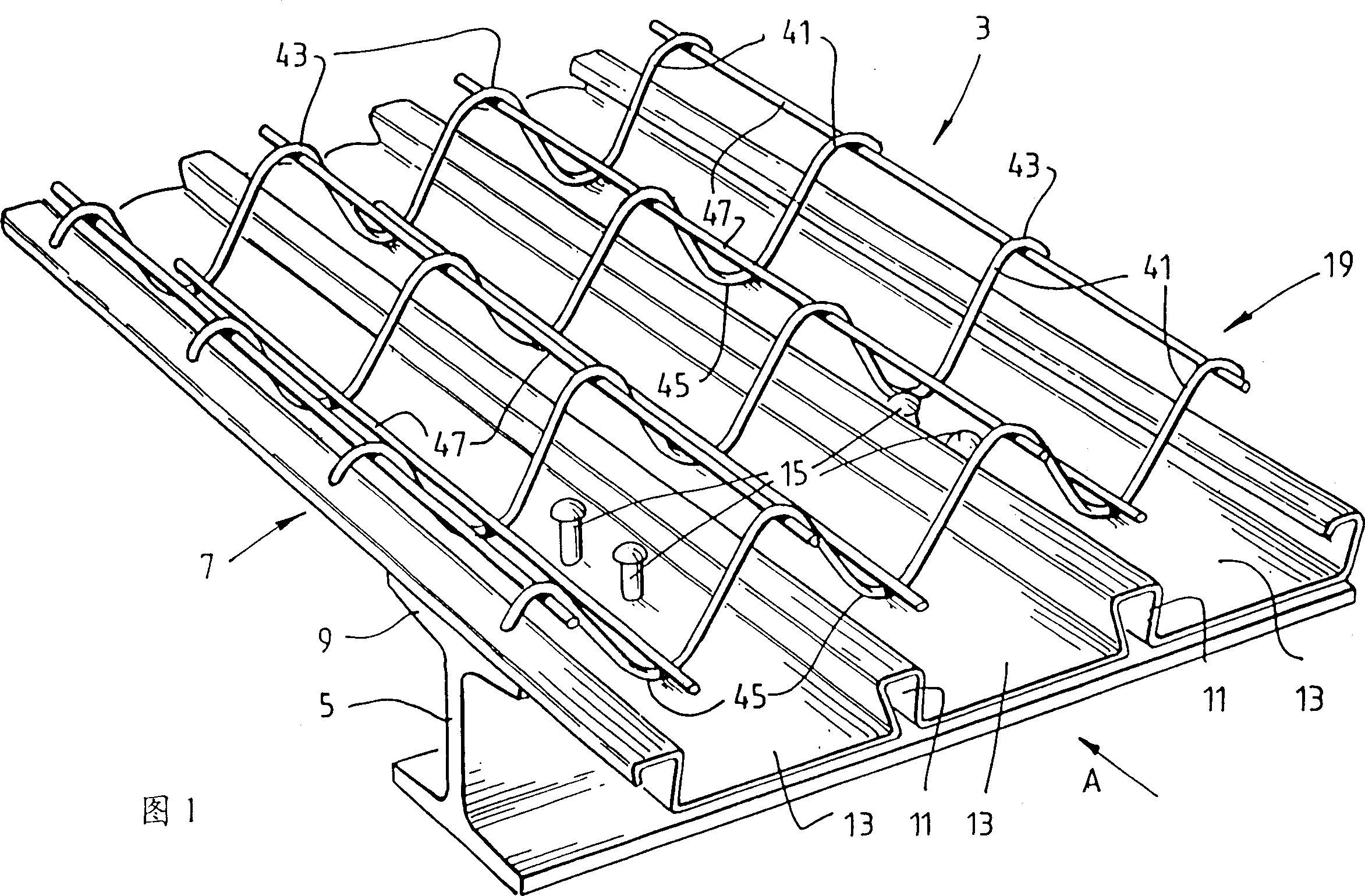
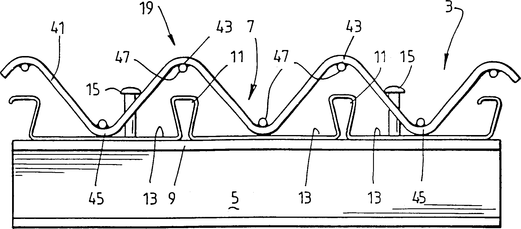
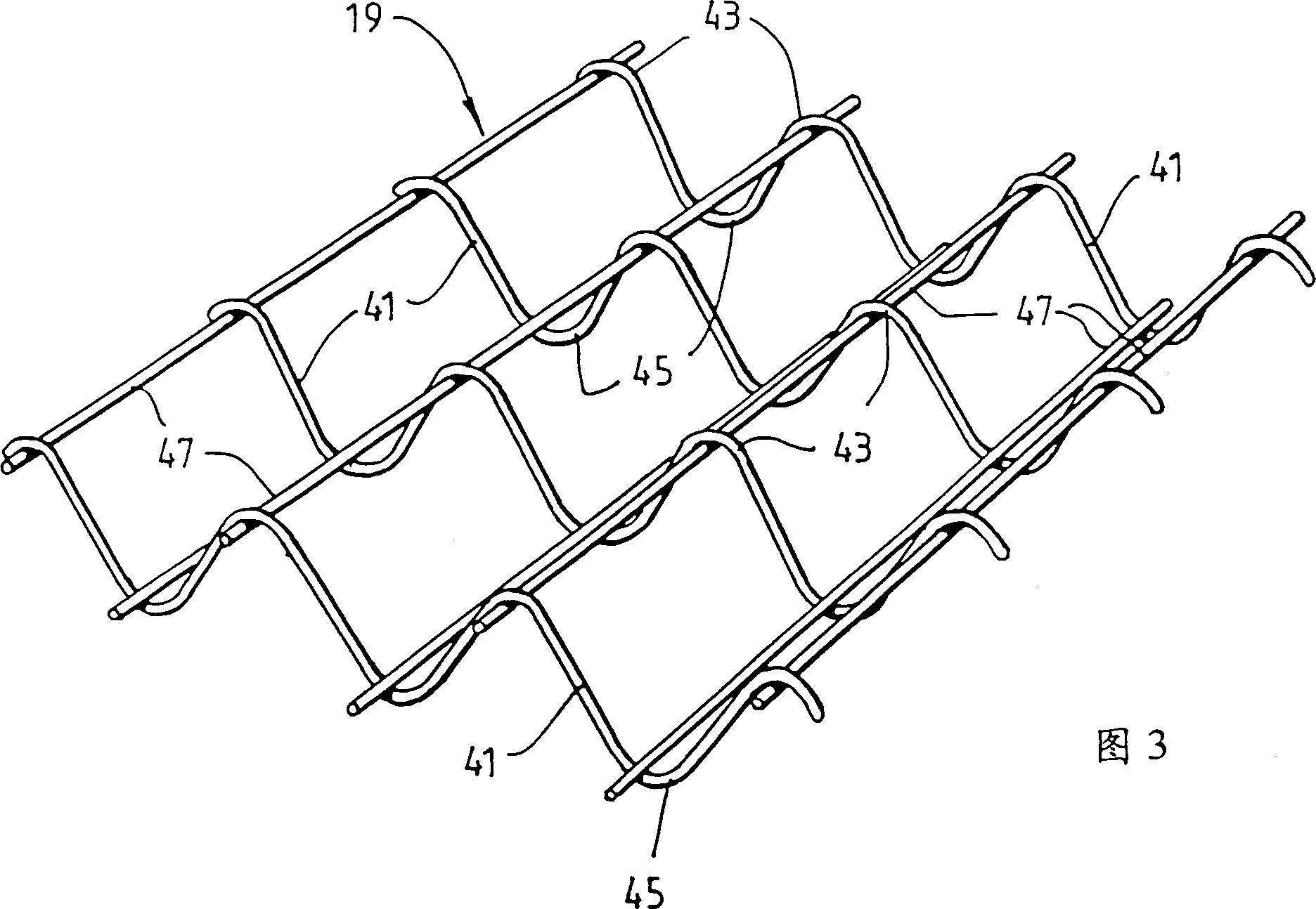
[0054] The preferred embodiment of the composite beam 3 of the present invention shown in FIGS. 1 to 3 illustrates the composite beam 3 more clearly in a simplified form.

[0055] With reference to accompanying drawing, the composition of composite beam 3 is:

[0056] (a) a horizontally extending hot-rolled or fabricated steel beam 5 supported at both ends;

[0057] (b) Composite panels, including:

[0058] (1) The shaped steel plate 7 that joins with the upper flange 9 of the steel girder 5, and the steel plate 7 includes many parallel arch bridges 11, separated by the flat part 13 between them, and the longitudinal direction of the arch bridge 11 relative to the steel girder 5 The axis is placed horizontally;

[0059] (II) concrete poured on the steel plate 7 (not shown);

[0060] (c) a number of shear connectors 15 in the form of braced studs passing through the steel plate 7 and welded to the upper flange 9 of the steel beam 5; and

[0061] (d) Reinforcement 19 in the ...


PUM


Abstract

A composite beam(3) for the building industry is disclosed. The composite beam(3) comprises: a horizontally extending beam(5); a composite slab formed from profiled sheeting(7) and concrete cast on the sheeting(7); a plurality of shear connectors(15) extending through the sheeting(7) and welded to the top flange(9) of the beam(5); and a reinforcing component(19) in the concrete slab for preventing premature longitudinal shear failure of the composite beam(3).

Description

technical field [0001] This invention relates to composite beams for the construction industry. [0002] The term "composite beam" is here understood to mean a beam, preferably made of steel, connected by shear connections to a monolithic or composite slab so as to function as a single structural member. [0003] The term "shear-resistant connection" is here understood to mean the interconnection between a beam of a composite beam and a monolithic or composite slab, such that the two parts together form a single structural member. [0004] The invention relates in particular to such composite beams comprising: [0005] (a) Beams (usually steel) supported at both ends; [0006] (b) Composite slabs placed over and supported by steel beams comprising: [0007] (I) Formed sheet metal (generally steel); [0008] (II) concrete poured over the steel plate; and [0009] (III) Rebar embedded in concrete. [0010] (c) A large number of shear-resisting connections, typically cap st...

Claims


Application Information

Patent Timeline
IPC IPC(8): E04B5/29E04B5/40E04C5/06
CPCE04B5/40E04B5/29E04C5/0636
Inventor 马克·帕特里克佩德鲁·H·达亚万萨
Owner BHP STEEL PTY LTD
Learn More