Method of lock catch type vacuum rolling metal composite plate

A metal clad plate, vacuum rolling technology, applied in the direction of metal rolling, metal rolling, metal processing equipment, etc., to increase the composite strength, improve the rolling stability, and reduce the oxidation of the joint interface.

Inactive Publication Date: 2014-01-08
武汉钢铁有限公司
View PDF10 Cites 18 Cited by
  • Summary
  • Abstract
  • Description
  • Claims
  • Application Information

AI Technical Summary

Problems solved by technology

[0012] The purpose of the present invention is to solve the defects of the existing metal clad plate rolling process, and provide a method for locking vacuum rolling metal clad plate

Method used


Image

  • Method of lock catch type vacuum rolling metal composite plate
  • Method of lock catch type vacuum rolling metal composite plate
  • Method of lock catch type vacuum rolling metal composite plate

Examples


Embodiment 1

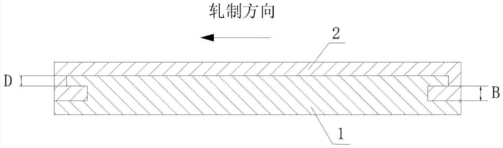
[0033] like Figure 1~3 The method of locking type vacuum rolling metal clad plate shown in, realizes through the following steps:

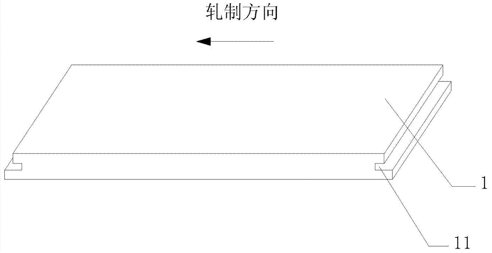
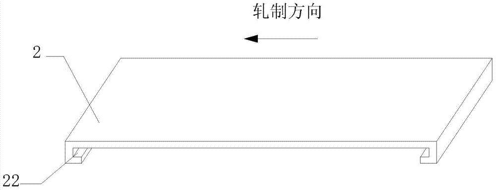
[0034] 1) Select the base plate 1 and the cladding plate 2 with the same width for processing, respectively process the through grooves 11 on both end faces of the base plate 1 perpendicular to the rolling direction, so that the longitudinal section of the base plate 1 after processing is I-shaped; The L-shaped fitting strips 21 are respectively welded at the positions corresponding to the grooves 11 at the two ends of the cladding plate 2 perpendicular to the rolling direction; With corresponding cooperation, the grooves 11 at both ends of the substrate 1 have the same depth;

[0035] 2) Clean the surface to be compounded of the substrate 1 and the cladding 2 to remove surface oil stains; slide the L-shaped fitting strips 21 at both ends of the cladding 2 into the grooves 11 at both ends of the substrate 1 along the direction perpendicular to t...

Embodiment 2

[0044] like Figure 2~4 As shown, the present embodiment is substantially the same as embodiment 1, except that embodiment 2 is to prepare stainless steel-carbon steel double-sided composite panels by this method, that is, substrate 1 adopts a Q345 carbon steel plate with a length of 1200mm × width of 600mm × thickness of 60mm; 2 Two pieces of 304 stainless steel plates are used with a thickness of 10mm; a groove 11 is processed on the carbon steel substrate 1 with a width of 30mm at the bottom, and the distance between the groove 11 and the upper surface of the carbon steel substrate 1 is 15mm; L is processed on both sides of the stainless steel cladding plate 2 Shape fitting bar 21, L-shaped fitting bar 21 height is 15mm. Slide the L-shaped fitting strip 21 into the groove 11 perpendicular to the rolling direction, so that the two cladding plates 2 are attached to the upper and lower surfaces of the base plate 1 respectively to form a composite slab, and the two sides of the...

Embodiment 3

[0046] like Figure 1~3 As shown, this embodiment is substantially the same as that of Embodiment 1, except that in Embodiment 3, a carbon steel extra-thick composite plate is prepared by this method, that is, both the base plate 1 and the cladding plate 2 are Q345 carbon steel plates with a length of 1000 mm × width of 600 mm × thickness of 200 mm , processing a groove 11 on the substrate 1 with a bottom width of 25mm, and the groove 11 is 50mm away from the upper surface of the substrate 1; L-shaped fitting strips 21 are processed on both sides of the cladding plate 2, and the size of the L-shaped fitting strip 21 is the same as that of the groove 11 consistent size. Slide the L-shaped fitting strip 21 into the groove 11 along the direction perpendicular to the rolling direction, so that the base plate 1 and the cladding plate 2 form a composite slab, and weld the sealing and welding plates on both sides of the composite slab, so that the base plate 1 and the cladding plate ...


PUM


Abstract

A method of a lock catch type vacuum rolling metal composite plate comprises the following steps that penetrated grooves are machined in the end faces of the two ends, vertical to the rolling direction, of a base plate respectively, and correspondingly, L-shaped embedding strips are welded to corresponding positions at the two ends of a shroud plate respectively; greasy dirt on the surface to be compounded is cleaned; the L-shaped embedding strips at the two ends of the shroud plate slide into the grooves in the two ends of the base plate to enable a composite slab formed by the shroud plate and the base plate to be in an embedded state. Sealing plates are connected to the periphery of the composite slab in a welded mode to enable composite space to be sealed; holes are formed in the sealing plates, air between the shroud plate and the base plate is extracted through the holes, and the holes are blocked after vacuum pumping is carried out; the composite slab is heated to 950-1300 DEG C to be rolled until the composite slab reaches a needed thickness to form the metal composite plate; edge cutting is carried out on the rolled metal composite plate, the sealing plates are removed, and rolling of the composite plate is completed. According to the method, mutual movement of adjacent slabs in the rolling direction and the slab thickness direction can be effectively constrained, rolling stability is improved, and meanwhile composite strength of the metal composite plate is greatly increased.

Description

technical field [0001] The invention relates to a rolling method of a metal composite plate, in particular to a lock-type vacuum rolling method for a metal composite plate. Background technique [0002] Metal composite panels are composited by two or more metal panels with different properties through special preparation methods. Compared with single metal components, metal composite panels after rational design and combination combine the respective advantages of metal components, and can obtain mechanical, physical and chemical properties that single metals do not have. In recent decades, the development, production and application of metal composite panels have attracted more and more attention. So far, this composite material has been widely used in aerospace, petroleum, chemical industry, metallurgy, machinery, automobile, ship, construction and other fields. [0003] The preparation methods of metal clad plates mainly include: explosive cladding method, casting metho...

Claims


Application Information

Patent Timeline
Patent Type & Authority Applications(China)
IPC IPC(8): B21B1/38B21B47/00
Inventor 汪荣韩斌汪水泽魏兵杨奕
Owner 武汉钢铁有限公司
Why Eureka
Try Eureka