Pressing capillary system type refill assembly and writing pen

A direct-liquid, component-based technology, applied in the field of stationery, can solve problems such as seal failure, ink volatilization, and insufficient sealing force of writing balls, and achieve the effect of avoiding ink leakage, avoiding volatilization, and better and more reliable sealing effect

Pending Publication Date: 2020-12-18
QINGDAO DIANSHI STATIONERY
View PDF1 Cites 4 Cited by
  • Summary
  • Abstract
  • Description
  • Claims
  • Application Information

AI Technical Summary

Problems solved by technology

Its disadvantage is that once the assembly is poor or the processing of the water diversion core is poor, the force of the spring will be lost, resulting in insufficient sealing force of the writing ball
In other words, once the ink guide core is worn, or the processing is a little bit off, or the assemb

Method used


Image

  • Pressing capillary system type refill assembly and writing pen
  • Pressing capillary system type refill assembly and writing pen
  • Pressing capillary system type refill assembly and writing pen

Examples


Embodiment 1

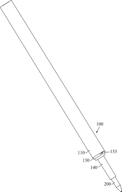
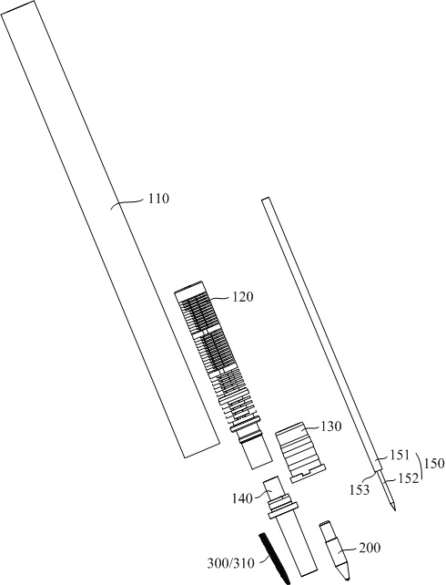
[0047] refer to Figure 1 to Figure 3 , The tilting straight liquid refill assembly in this embodiment mainly includes the ink cartridge assembly 100 , the nib 200 , the elastic member 300 and other parts.

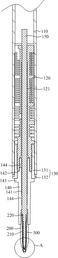
[0048] The ink cartridge assembly 100 is provided with an ink lead core 150, and the ink cartridge assembly 100 is used for storing ink and leading ink, leading the ink to the nib 200 for writing.

[0049] The nib 200 is arranged at one end of the ink cartridge assembly 100, and the inside of the nib 200 is formed with a penetrating ink flow channel 210, and the ink outlet end of the ink flow channel 210 is provided with a ball portion 230, and the ink leading core 150 has a part penetrating the ink flow channel 210. , One end of the ink lead 150 abuts against the ball portion 230 . The ink cartridge assembly 100 guides the ink into the ink flow channel 210 and reaches the ball portion 230 , and utilizes the shearing and rolling of the ink by the ball portion 230 to achie...

Embodiment 2

[0081] The difference between the second embodiment and the first embodiment lies in the arrangement of the ball portion 230 , and the other structures are the same, so only the ball portion 230 will be described in detail below.

[0082] In embodiment two, refer to Figure 5 , the ball portion 230 is a double-ball structure, including an upper ball 231 and a lower ball 232, the upper ball 231 abuts against the lower ball 232, the conical spring 310 abuts against the upper ball 231, and the ink core 150 Abut against the upper ball 231.

[0083] The conical spring 310 directly acts on the upper ball 231, and the upper ball 231 directly acts on the lower ball 232 to form a power transmission, so that a contact seal is formed between the lower ball 232 and the inner wall of the ink flow channel 210 to avoid ink leakage. Evaporation and ink leakage.

[0084] The conical spring 310 bears against the upper ball 231, no matter how well the conical spring 310 and the upper ball 231 ...

Embodiment 3

[0087] This embodiment provides a writing pen, which includes the tilting direct liquid refill assembly disclosed in Embodiment 1 and Embodiment 2.


PUM


Abstract

The invention discloses a pressing capillary system type refill assembly and a writing pen. The pressing capillary system type refill assembly comprises an ink barrel assembly, a pen point and an elastic piece, wherein an ink leading core is arranged in the ink barrel assembly, the pen point is arranged at one end of the ink barrel assembly, a through ink flowing channel is formed inside the pen point, a ball bead portion is arranged at the ink outlet end of the ink flowing channel, the ink leading core partially penetrates through the ink flowing channel, one end of the ink leading core abutsagainst the ball bead portion, the elastic piece is arranged on the periphery of the ink leading core in a sleeve mode and located in the ink flowing channel, the elastic piece abuts against the ballbead portion to apply acting force enabling the ball bead portion to abut against the inner wall of the ink outlet end, contact sealing is formed between the ball bead portion and the inner wall of the ink outlet end, and ink volatilization and ink leakage are avoided.

Description

technical field [0001] The invention relates to the technical field of stationery, in particular to a tilting straight liquid refill assembly and a writing pen. Background technique [0002] Compared with gel pens, traditional straight-liquid water-based ballpoint pens have the advantages of longer writing length (3-5 times that of ordinary gel pens), uniform inking, and smooth hand feeling. However, due to the use of water-based ink, it is easy to evaporate and dry up, so the traditional straight-liquid water-based ballpoint pens all adopt the cap-pull seal design. There is a problem that the pen cap is easy to lose, and once the seal of the pen cap leaks, the product is very easy to dry ink and leak ink. And the push-type straight-liquid water-based ballpoint pen, because it is a push-type structure, does not need a pen cap, which can solve the above hidden dangers and problems. [0003] Chinese patent CN200780033045.7 discloses a writing tool, which is also a tilting st...

Claims


Application Information

Patent Timeline
IPC IPC(8): B43K7/10
CPCB43K7/10B43K1/082B43K11/00
Inventor 王元鸿
Owner QINGDAO DIANSHI STATIONERY
Why Eureka
Try Eureka