
Limiting scraper type automatic discharging equipment and discharging method

An automatic discharge and scraper-type technology, applied in the direction of loading/unloading, conveyors, mechanical conveyors, etc., can solve the problems of large dust, poor working conditions, and low automation, and achieve simple control, improved efficiency, and easy implementation Effect

Pending Publication Date: 2020-12-18
NEW METALLURGY HI TECH GRP
View PDF9 Cites 0 Cited by
  • Summary
  • Abstract
  • Description
  • Claims
  • Application Information

AI Technical Summary

Problems solved by technology

[0004] In view of the above analysis, the present invention aims to provide a limited scraper type automatic discharge equipment and a discharge method to solve the problems of large dust, poor working conditions and low degree of automation in the current high-temperature powder and granular material discharge process

Method used


Image

  • Limiting scraper type automatic discharging equipment and discharging method

Examples


Embodiment 1

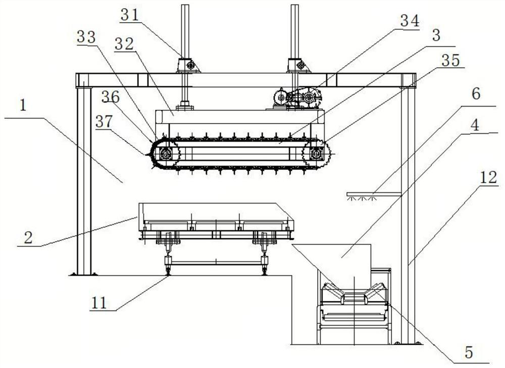
[0035] An embodiment of the present invention, such as figure 1 As shown, a limited scraper type automatic discharge equipment is disclosed, including a discharge bin 1, a loading trolley 2, a discharge unit 3, a receiving bucket 4, an ash conveying device 5 and a dust reduction device 6, which can realize the Quick unloading and cleaning in high temperature closed environment.

[0036] For illustrative purposes, figure 1 The left side of the direction shown is left, the right side is right, the direction with the horizontal plane up is up, and the direction with the horizontal plane down is down.

[0037] This embodiment is applied to the unloading of high-temperature powdery soil in the tunnel kiln soil restoration process. The unloading bin 1 is located at the end of the heat treatment section of the tunnel kiln. The unloading bin 1 is connected to the tunnel kiln body to ensure that the loading trolley 2 can run to the set position of the unloading bin 1 through the inne...

Embodiment 2

[0053] One embodiment of the present invention discloses a discharging method of a limit scraper type automatic discharging device, comprising the following steps:

[0054] S1. The loading trolley 2 enters the unloading bin 1:

[0055] A plurality of loading trolleys 2 are arranged in sequence in the tunnel kiln, and a propulsion mechanism is provided in the tunnel kiln. Driven by the propulsion mechanism, the loading trolleys 2 enter the unloading bin 1 along the loading trolley track 11, and the propulsion mechanism Each time the loading trolley 2 is pushed forward by the length of one loading trolley, the advancing frequency is 5-20min / time.

[0056] S2, unloading unit 3 starts and begins to descend:

[0057] A limit switch is provided at the position corresponding to the unloading unit 3 on the track 11 of the loading trolley. After the loading trolley 2 enters the corresponding position of the unloading bin 1, the limit switch is triggered, thereby starting the unloading...


PUM


Abstract

The invention relates to limiting scraper type automatic discharging equipment and a discharging method, belongs to the technical field of discharging sweeping equipment, and solves the problems of large dust, poor working condition and low automation degree in the existing high-temperature powder and particle material discharging process. The limiting scraper type automatic discharging equipmentcomprises a discharging bin, a material carrying trolley, a discharging unit and a receiving hopper. The discharging unit and the receiving hopper are located in the discharging bin, the material carrying trolley can convey materials to the discharging bin, and the discharging unit can scrape and sweep the materials in the material carrying trolley into the receiving hopper. According to the limiting scraper type automatic discharging equipment and the discharging method, the material carrying trolley is used for conveying high-temperature materials to the discharging bin, the discharging unitof the discharging bin is started, the high-temperature materials in the material carrying trolley are scraped and swept into the receiving hopper, and an ash conveying device located below the receiving hopper conveys the materials out of the discharging bin. Therefore, the high-temperature materials can be quickly discharged and swept in a closed environment.

Description

technical field [0001] The invention relates to the technical field of discharging and cleaning equipment, in particular to a limit scraper type automatic discharging device and a discharging method. Background technique [0002] Tunnel kilns and belt furnaces are often used in the heat treatment process of powdery and granular materials. Among them, the tunnel kiln adopts refractory material structure and can achieve a material processing temperature above 900°C. According to the state of the material after heat treatment, the discharge method is mainly divided into two types: (1) For hot-melt or semi-molten materials, there are outflow discharge process, siphon discharge process, spiral discharge process, or material cooling (2) For solid materials, the process of manually pushing out after cooling is usually adopted. Materials are usually cooled for a period of time after heating treatment to reduce the impact on the discharge equipment or improve the manual discharge en...

Claims


Application Information

Patent Timeline
Patent Type & Authority Applications(China)
IPC IPC(8): B65G67/24B65G69/18B65G35/00B65G69/08
CPCB65G35/00B65G67/24B65G69/08B65G69/181B65G2201/04
Inventor 潘聪超庞建明邸久海赵志民罗林根刘飞
Owner NEW METALLURGY HI TECH GRP
Learn More