Waste filament treatment mechanism for filament covering machine

A technology for wrapping silk machine and waste silk, which is applied in textiles and paper making, etc., can solve the problems of low resource utilization rate, falling in, and waste silk cannot be reused, and achieves the effect of improving separation effect and dust removal effect.

Active Publication Date: 2020-12-18
杭州麒隆化纤有限公司
View PDF10 Cites 9 Cited by
  • Summary
  • Abstract
  • Description
  • Claims
  • Application Information

AI Technical Summary

Problems solved by technology

[0004] In view of the above-mentioned related technologies, the inventor believes that there is the following defect: because there is more dust in the production workshop and on the workbench, so the dust and waste silk will fall into the waste silk collection box together, and the waste silk with more dust will fall into the waste silk collection box. Silk cannot be reused, resulting in low resource utilization, so it needs to be improved

Method used


Image

  • Waste filament treatment mechanism for filament covering machine
  • Waste filament treatment mechanism for filament covering machine
  • Waste filament treatment mechanism for filament covering machine

Examples


Embodiment Construction

[0037] The following is attached Figure 1-6 The application is described in further detail.

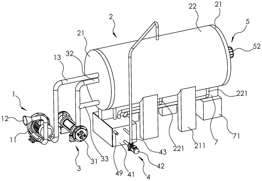
[0038] The embodiment of the present application discloses a waste silk processing mechanism of a covered silk machine. Such as figure 1 As shown, a waste silk processing mechanism of a covered silk machine includes a suction assembly 1, a separation assembly 2, an air jet assembly 3 and a spray assembly 4, and the suction assembly 1 is used to suck waste silk and dust into the separation In the assembly 2, the air jet assembly 3 is used to separate the waste silk and the dust in the separation assembly 2, and the spray assembly 4 is used to spray and remove the dust in the separation assembly 2.

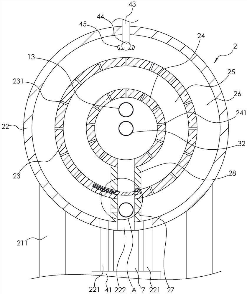
[0039] Such as figure 1 with figure 2 As shown, the separation assembly 2 includes two fixed plates 21 arranged in sequence along the horizontal direction, an outer cylinder 22 between the two fixed plates 21, an inner cylinder 23 and a rotating cylinder 24, and both ends of the outer...


PUM


Abstract

The invention relates to the technical field of filament covering machines, in particular to a waste filament treatment mechanism for a filament covering machine. The filament treatment mechanism comprises a separation assembly, a material suction assembly and an air injection assembly; the separation assembly comprises two fixing plates, an outer cylinder and an inner cylinder, wherein an outer dust cavity is arranged between the inner wall of the outer cylinder and the outer wall of the inner cylinder, a plurality of dust discharge pipes are fixed on the outer wall of the outer cylinder, a plurality of first dust discharge through holes are formed in the inner wall of the inner cylinder, notches are formed in the bottoms of the outer cylinder and the inner cylinder separately, and two first partition plates are fixedly embedded in the outer dust cavity; the material suction assembly comprises a fan, a feeding pipe and a discharging pipe; the air injection assembly comprises an air pump and a first air injection pipe, wherein an air injection area and a closed area are arranged on the outer wall of the first air injection pipe, and a plurality of first air injection holes are formed in the air injection area. In the waste filament collecting process, the air pump prompts dust to penetrate through the first dust discharge through holes to enter the outer dust cavity and be discharged from the dust discharge pipes, and waste filaments are discharged from the notches of the inner cylinder and the outer cylinder. According to the mechanism, the dust is separated from the wastefilaments.

Description

technical field [0001] The present application relates to the technical field of a covered wire machine, in particular to a waste wire processing mechanism of a covered wire machine. Background technique [0002] Covering silk machine is a device used to spirally wind silk, polyester and other chemical fiber filaments and cotton wool and other fibers on the spandex core wire. The covered yarn produced by the coated yarn machine not only has the elasticity of spandex, but also has the appearance and good hand feeling of coated yarn, which provides an ideal coated yarn raw material for the production of elastic fabrics and knitted fabrics. [0003] Through retrieval, Chinese Patent Publication No. CN207793514U discloses a waste silk collection device of a covered silk machine, comprising a covered silk machine body, a support plate is fixedly connected to the right side of the covered silk machine body, and the support plate The top is fixedly connected with a driving motor, ...

Claims


Application Information

Patent Timeline
Patent Type & Authority Applications(China)
IPC IPC(8): D01H11/00
CPCD01H11/00
Inventor 徐柏寅曹招明
Owner 杭州麒隆化纤有限公司
Why Eureka
Try Eureka