High-speed railway bridge assembly type damping device and application method and replacement method thereof

A high-speed railway and damping device technology, applied in the field of bridge damping, can solve problems such as difficulty in dismantling and replacement, difficulty in monitoring deformation, unfavorable seismic performance of bridge structures, etc.

Active Publication Date: 2020-12-18
CENT SOUTH UNIV
View PDF8 Cites 2 Cited by
  • Summary
  • Abstract
  • Description
  • Claims
  • Application Information

AI Technical Summary

Problems solved by technology

[0005] Most of them have complex structures and are often integrally connected with the bridge structure. The construction cost is relatively high, and the removal and replacement are difficult and time-consuming, which is not conducive to the rapid recovery of the seismic performance of the bridge structure after the earthquake;
[0006] Energy is consumed through bending deformation, which is not easy to be monitored, which is not conducive to bridge structural health monitoring and damage identification

Method used


Image

  • High-speed railway bridge assembly type damping device and application method and replacement method thereof
  • High-speed railway bridge assembly type damping device and application method and replacement method thereof
  • High-speed railway bridge assembly type damping device and application method and replacement method thereof

Examples


Embodiment Construction

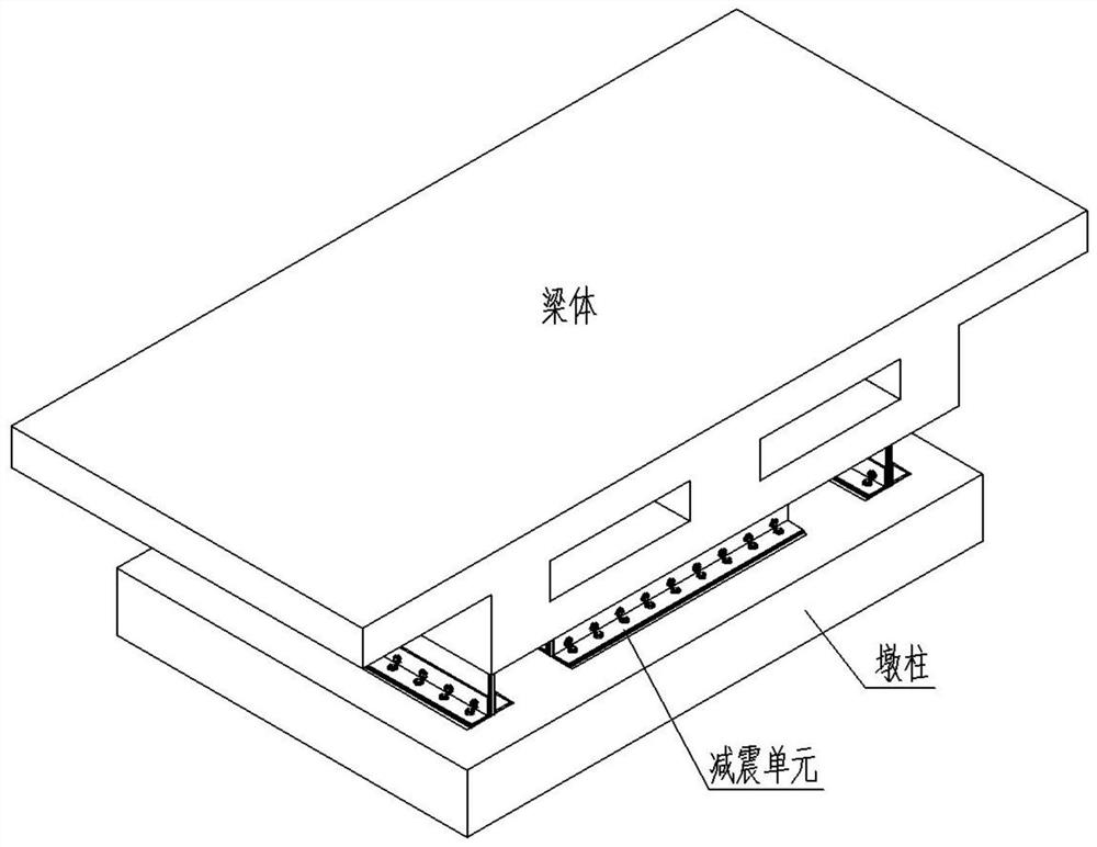
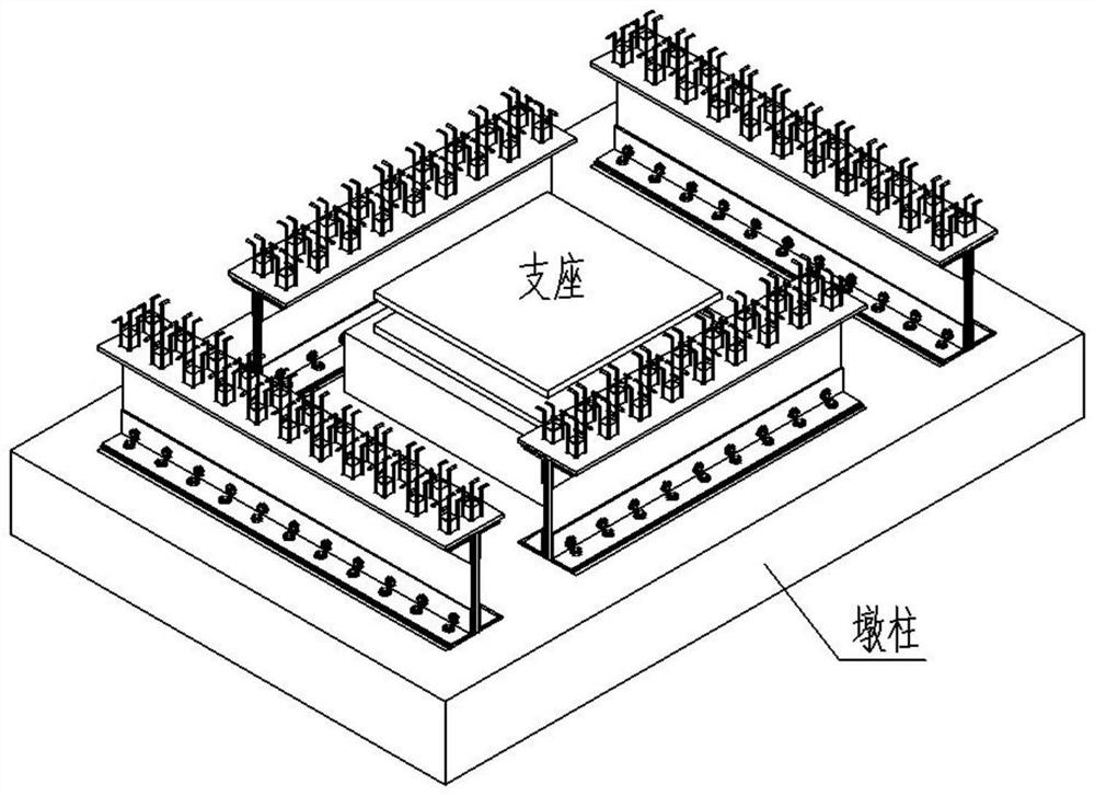
[0036] combine figure 1 , figure 2 It can be seen that the high-speed railway bridge assembly-type steel plate shear wall damping device disclosed in this embodiment includes multiple sets of damping units arranged around the support at the center of the top of the pier column.

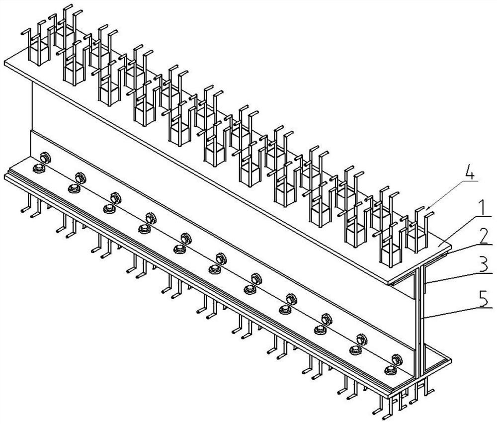
[0037] combine Figure 1 to Figure 3 It can be seen that each group of damping units includes two sets of T-shaped main body 1 and its connected horizontal energy-dissipating plate 2, angle steel 3, anchor member 4 and fastener assembly components. Relatively arranged, the vertical energy dissipation plate 5, angle steel 3 and fasteners are connected to form an integral part with an I-shaped cross-section of the assembled main structure.

[0038] combine image 3 with Figure 4 It can be seen that the top surface of the wing plate of the T-shaped main body 1 is symmetrically connected with two rows of anchor members 4 with respect to its longitudinal center plane, and the horizontal energy dissip...


PUM


Abstract

The invention discloses a high-speed railway bridge assembly type steel plate shear wall damping device. The high-speed railway bridge assembly type steel plate shear wall damping device is characterized in that an anti-seismic support is arranged in the center of the top of a prefabricated pier column, the damping device comprises a plurality of sets of damping units evenly distributed around theanti-seismic support, and each set of damping unit comprises T-shaped bodies, horizontal energy dissipation plates, angle steel, vertical energy dissipation plates and anchoring components; the horizontal energy dissipation plates are symmetrically arranged on the inner sides of wing plates of the T-shaped bodies, angle steel is symmetrically arranged on the two sides of webs, the corners of theangle steel are located in included angles between the wing plates and the webs of the T-shaped bodies, and the two rows of anchoring components symmetrical with respect to the center face in the length direction are arranged on the outer sides of the wing plates. The wing plates of the T-shaped main bodies, the horizontal energy dissipation plates, horizontal arms of the angle steel and the anchoring components are connected through high-strength bolts and nuts to form an integral pieces; and the two sets of integrated pieces are symmetrically arranged relative to the webs of the T-shaped bodies, and after the vertical energy dissipation plates are inserted into the two sides of the webs of the two T-shaped bodies and between vertical arms of the angle steel on the two sides separately, the damping units are formed through the high-strength bolts and nuts in a connected mode.

Description

technical field [0001] The invention belongs to the field of bridge damping, in particular to an assembled damping device for a high-speed railway bridge, an application method and a replacement method thereof. Background technique [0002] The direct damage caused by the earthquake to the bridge is the damage and collapse of the bridge structure. The connection nodes between the bottom surface of the bridge beam body and the top of the pier column are the weak link of the bridge structure and the key link of the seismic design. [0003] In recent years, with the continuous development of anti-seismic bearing technology, anti-seismic bearing technologies such as lead rubber anti-seismic bearings and pendulum sliding friction bearings have been continuously developed in the engineering practice of bridge anti-seismic. seismic load. In order to ensure the safety of seismic bearings, shock-absorbing tenons are often installed in projects to dissipate part of the seismic energy...

Claims


Application Information

Patent Timeline
Patent Type & Authority Applications(China)
IPC IPC(8): E01D19/00E01D19/04F16F15/02
CPCE01D19/00E01D19/04F16F15/02
Inventor 江力强喻凯蒋丽忠
Owner CENT SOUTH UNIV
Why Eureka
Try Eureka