Diesel engine water tank structure

A diesel engine and water tank technology, which is applied in mechanical equipment, engine components, engine cooling, etc., can solve the problems of high labor intensity, low cleaning efficiency, time-consuming and laborious, etc., and achieve low labor intensity, high degree of automation, and good cleaning effect Effect

Inactive Publication Date: 2020-12-18
JIANGSU XINHAI SCI & TECH DEV CO LTD
View PDF0 Cites 2 Cited by
  • Summary
  • Abstract
  • Description
  • Claims
  • Application Information

AI Technical Summary

Problems solved by technology

During the use of existing diesel engine water tanks, impurities in the water will form scale after long-term accumulation on the inner wall of the water tank. If the scale is not cleaned regularly, once the scale is peeled off in a large area, the water outlet of the diesel engine will be blocked, resulting in poor water supply. Due to the adhesion of scale It is relatively strong. At present, the shovel is inserted into the water tank manually for eradication. The labor intensity is high, the cleaning efficiency is low, and time-consuming and laborious. At the same time, the existing diesel engine water tanks are installed on the diesel engine by fixed support. The water tank will vibrate during cleaning and when the water tank is cleaned. During the vibration process, the fixed support part of the water tank is easy to loosen and break, and the use effect is not ideal.

Method used


Image

  • Diesel engine water tank structure
  • Diesel engine water tank structure

Examples


Embodiment Construction

[0013] The specific content of the present invention will be described in detail below in conjunction with the accompanying drawings and specific embodiments.

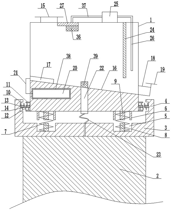
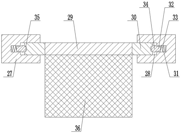
[0014] like figure 1 , figure 2 As shown, the diesel engine water tank structure includes: a water tank body 1 and a diesel engine 2, a buffer base 3 is arranged on the upper end of the diesel engine 2, and buffer side plates 4 are respectively arranged around the buffer base 3, and on the buffer base The lower spring groove 5 is symmetrically arranged on both sides of the upper end of 3, and an upper spring seat 6 is correspondingly arranged on the water tank body 1 at the upper end of the lower spring groove 5, and a spring seat 6 is arranged between the lower spring groove 5 and the upper spring seat 6. The first buffer spring 7, one end of the first buffer spring 7 is against the buffer base 4, the other end of the first buffer spring 7 is against the water tank body 1, and the buffer base inside one end of the f...


PUM


Abstract

The invention discloses a diesel engine water tank structure. The structure comprises a water tank body and a diesel engine, a buffer base is arranged at the upper end of the diesel engine, buffer side plates are arranged at the periphery of the buffer base, and lower spring grooves are symmetrically formed at the two sides of the upper end of the buffer base. Upper spring seats are correspondingly arranged at the positions, located at the upper ends of the lower spring grooves, of the water tank body, first buffer springs are arranged between the lower spring grooves and the upper spring seats, one ends of the first buffer springs abut against the buffer base, and the other ends of the first buffer springs abut against the water tank body; and a lower spring guide supporting column is arranged at the portion, inside one end of each first buffer spring, of the buffer base, an upper spring guide supporting column is arranged at the portion, inside the other end of each first buffer spring, of the water tank body, and first side spring grooves are formed in the buffer side plates respectively.

Description

technical field [0001] The invention relates to a diesel engine, in particular to a diesel engine water tank structure. Background technique [0002] Diesel engine is an internal combustion engine that uses diesel as fuel, and a series of devices that convert the heat energy released by fuel combustion into electrical energy or mechanical energy. Diesel engines are mainly used in agricultural machinery, construction machinery, automobile industry, ship machinery, electric power industry and other fields. During the use of existing diesel engine water tanks, impurities in the water will form scale after long-term accumulation on the inner wall of the water tank. If the scale is not cleaned regularly, once the scale is peeled off in a large area, the water outlet of the diesel engine will be blocked, resulting in poor water supply. Due to the adhesion of scale It is relatively strong. At present, the shovel is inserted into the water tank manually for eradication. The labor i...

Claims


Application Information

Patent Timeline
Patent Type & Authority Applications(China)
IPC IPC(8): F01P11/00F01P11/06F01P5/10F16F15/067B08B3/08B08B3/12B08B3/14
CPCB08B3/08B08B3/12B08B3/14F01P5/10F01P11/00F01P11/06F01P2011/061F01P2011/063F01P2011/068F16F15/067
Inventor 徐海山黄长勇时一平张而耕周锦祥赵正东许向伍
Owner JIANGSU XINHAI SCI & TECH DEV CO LTD
Why Eureka
Try Eureka