Transmission shaft electric actuator with brake assembly

A technology of brake components and electric devices, applied in the direction of electromechanical devices, electric components, electrical components, etc., can solve the problems of high cost, small braking force, poor braking effect, etc., to prolong life, meet the needs of braking, and save use costs Effect

Pending Publication Date: 2020-12-18
深圳市博孚智能有限公司
View PDF0 Cites 0 Cited by
  • Summary
  • Abstract
  • Description
  • Claims
  • Application Information

AI Technical Summary

Problems solved by technology

[0002] There are two ways to brake in the prior art, one is to add a magnetic ring and a pure iron brake at the front or rear of the motor, and the other is a spring brake. The first brake force is relatively small and the brake effect is poor. The service life is short, frequent replacement, and high cost. To sum up, this application now proposes a transmission shaft electric device with a brake assembly to solve the above-mentioned problems

Method used


Image

  • Transmission shaft electric actuator with brake assembly
  • Transmission shaft electric actuator with brake assembly
  • Transmission shaft electric actuator with brake assembly

Examples


Embodiment

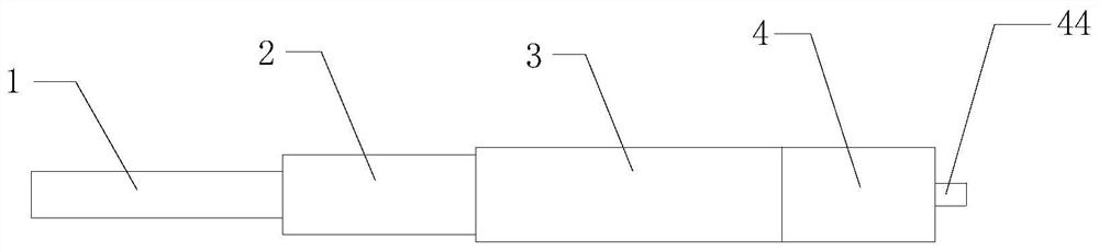
[0024] see Figure 1-Figure 6 , a transmission shaft electric device with a brake assembly, comprising a reducer 3, an electric motor 2, a control panel 1 and a brake assembly 4, the output shaft of the electric motor 2 is fixedly connected to the output shaft of the reducer 3, the The control board 1 is electrically connected with the electric motor 2 , the output shaft of the reducer 3 is inserted into the brake assembly 4 , and the brake assembly 4 is arranged at the low speed end of the reducer 3 .

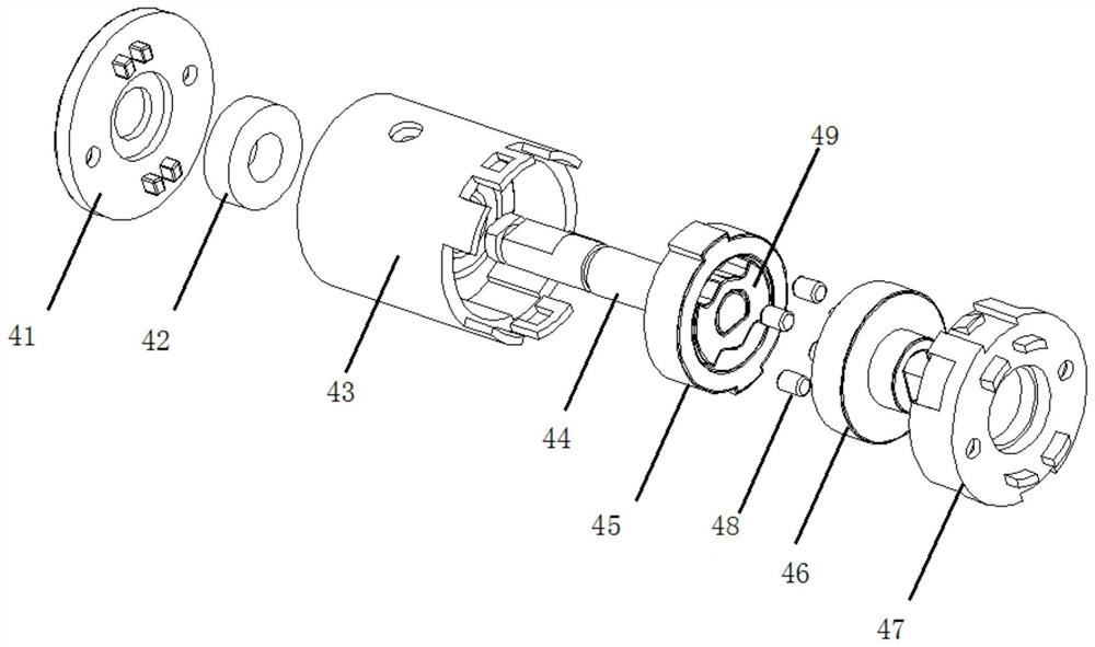
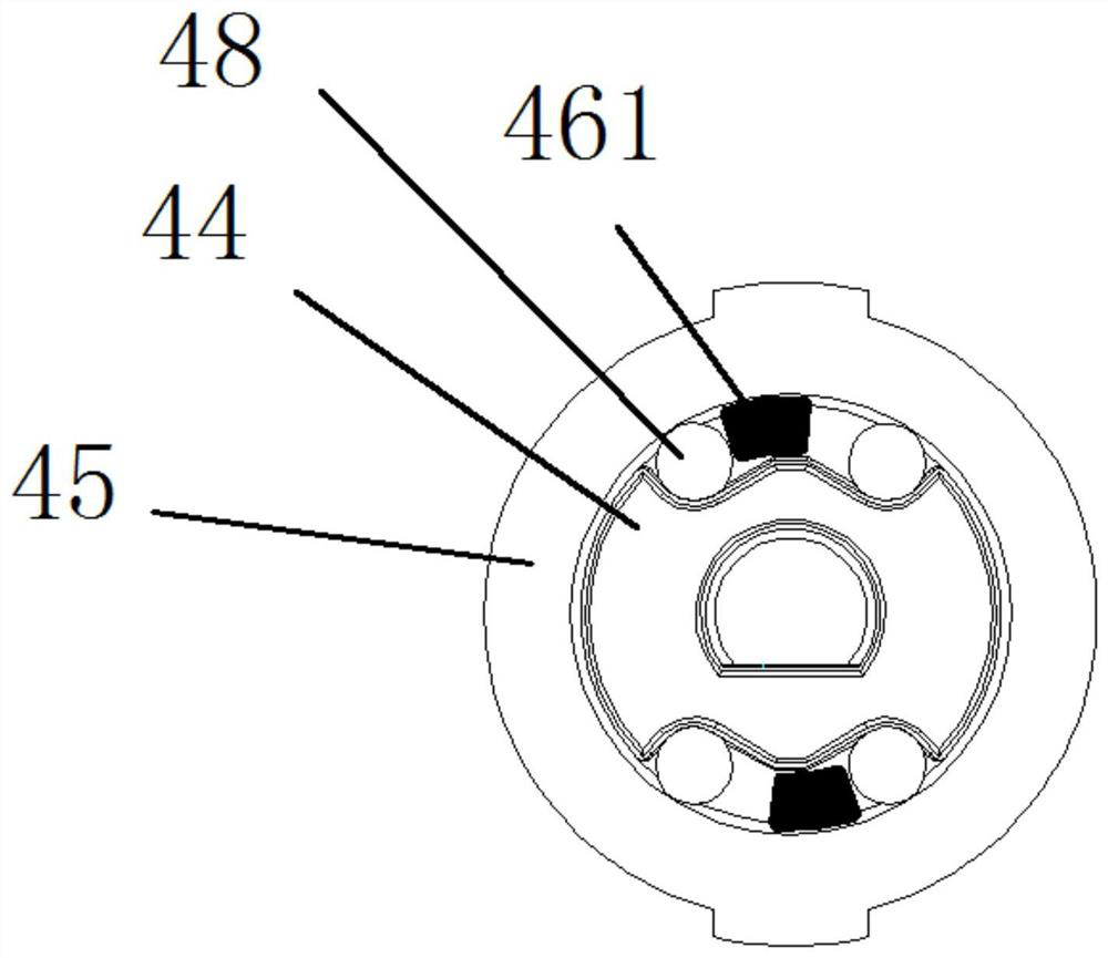
[0025] As an improvement of the above scheme, the brake assembly 4 includes a housing 43, an end cover 41, a cover plate 47, a fixed plate 45, a driven member 49, a transmission shaft 44, a driving member 46 and a roller 48, and the housing 43 and The reducer 3 is fixedly connected, the end cover 41 is arranged on the end of the casing 43 away from the reducer 3 , the cover plate 47 is arranged on the end of the casing 43 close to the reducer 3 , and the fixing plate 45 is fix...


PUM


Abstract

The invention provides a transmission shaft electric actuator with a brake assembly. The transmission shaft electric actuator with the brake assembly comprises a speed reducer, an electric motor, a control panel and the brake assembly; an output shaft of the electric motor is fixedly connected with an output shaft of the speed reducer; the control panel is electrically connected with the electricmotor; the output shaft of the speed reducer is inserted into the brake assembly; and the brake assembly is arranged at an lower speed end of the speed reducer. Through an outer shell, n end cover, acover plate, a driven piece, a fixed disc, a driving piece and a rolling shaft, a traditional braking mode is replaced, the braking force is guaranteed, the braking effect is guaranteed, meanwhile, the bouncing degree of a transmission shaft in the rotating direction can be reduced, the service life is prolonged, the braking requirement is met, and the use cost is saved.

Description

technical field [0001] One or more embodiments of this specification relate to the field of electric rotating shaft brake equipment, and in particular to an electric drive shaft device with a brake assembly. Background technique [0002] There are two ways to brake in the prior art, one is to add a magnetic ring and a pure iron brake at the front or rear of the motor, and the other is a spring brake. The first brake force is relatively small and the brake effect is poor. The service life is short, the replacement is frequent, and the cost is high. To sum up, the present application proposes a transmission shaft electric device with a brake assembly to solve the above-mentioned problems. Contents of the invention [0003] In view of this, the purpose of one or more embodiments of this specification is to provide an electric drive shaft device with a brake assembly, so as to solve the problems raised in the background art. [0004] Based on the above purpose, one or more em...

Claims


Application Information

Patent Timeline
IPC IPC(8): F16D49/00F16D65/16F16F15/124F16F15/16H02K7/10F16D121/26
CPCF16D49/00F16D65/16F16D2121/26F16F15/124F16F15/16H02K7/10
Inventor 王雨晴
Owner 深圳市博孚智能有限公司
Why Eureka
Try Eureka