Torque suction and discharge device based on elastic pin mechanism

A technology of spring needle and needle tip, applied in spring/shock absorber, mechanical equipment, vibration suppression adjustment, etc., can solve the problems of increased precision and production cost, reduced reliability, etc., to solve the problem of torque vibration, simple structure Effect

Active Publication Date: 2020-12-18
JIANJIAN TECH (NINGBO) CO LTD
View PDF6 Cites 6 Cited by
  • Summary
  • Abstract
  • Description
  • Claims
  • Application Information

AI Technical Summary

Problems solved by technology

These schemes have solved the torque matching problem to a certain extent, but have not completely overcome it, and the cost of the scheme is the increase of system weight, volume, complexity, precision and production cost and the reduction of reliability

Method used


Image

  • Torque suction and discharge device based on elastic pin mechanism
  • Torque suction and discharge device based on elastic pin mechanism
  • Torque suction and discharge device based on elastic pin mechanism

Examples


Embodiment 1

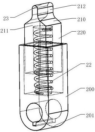
[0087] Such as figure 2 Shown is the radial sliding-cylindrical surface sliding fixed movable support pin, the movable support tail 210 is a fixed upright wall 211 with the cylinder as the top surface, and the generatrix of the cylinder is parallel to the main shaft axis of the movable support, wherein the fixed vertical Anti-falling walls or reinforcing ribs can also be added on both sides of the wall 211 . The fixed upright wall 211 and its reinforcing ribs are fixed on the movable support base 212, or are integrated with the movable support base 212. During work, the cylindrical surface is in sliding contact with the track surface 10, and the cylindrical surface is fixed relative to the movable support bottom 212.

Embodiment 2

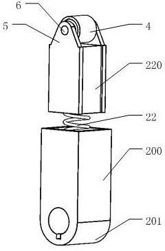
[0089] Such as image 3 and Figure 4 Shown are the radial sliding-cylindrical rolling fixed support spring pin and the radial fixed support side bearing rolling-cylindrical rolling fixed support spring pin respectively. The dynamic support tail 210 of this type of spring pin is composed of a top bearing 4, Two top bearing pedestals 5 and a top bearing shaft 6 are formed. The outer surface of the top bearing 4 is a cylindrical surface, the top bearing shaft 6 is fixed, and the top bearing shaft frame 5 is fixed on the bottom 212 of the movable support or is integrated with the bottom 212 of the movable support. The generatrix of the outer cylindrical surface of the top bearing 4 is parallel to the main shaft axis of the bullet pin. During work, the cylindrical surface of the top bearing 4 is in rolling contact with the track surface 10, and is fixed relative to the bottom 212 of the movable support.

Embodiment 3

[0091] Such as Figure 5 and Figure 6 Shown are a single top bearing moving bracket and a composite jacking bearing moving bracket respectively. The moving bracket tail 210 of this type of moving bracket 21 is composed of a top bearing 4 , two top bearing shaft frames 5 and a top bearing shaft 6 . The top bearing shaft 6 is fixed, the axis of the top bearing shaft 6 is parallel to the axis of the main shaft, and the top bearing shaft frame 5 is fixed on the movable support bottom 212 or integrated with the movable support bottom 212, which is parallel and symmetrical to the spring needle 2 Two upright walls passing through the center line of the compression spring 22 and perpendicular to the plane (the first symmetry plane of the spring pin) of the axis of the main shaft. The top bearing pedestal 5 can also have two upright walls that are parallel and symmetrical to the plane (the second symmetry plane of the pin) that the pin 2 passes through the center line of the clip spr...


PUM


Abstract

The invention discloses a torque suction and discharge device based on an elastic pin mechanism. The device comprises a rail and elastic pins; a rail surface of the rail has an axis of rotational symmetry in the geometry; the rail surface is a cylindrical surface or other curved surfaces formed by reducing rotation; each of the elastic pins comprises a fixed support, a movable support, and a pressure spring; the support bodies of the movable supports and of the fixed supports are embedded end to end, and the support bottoms of the movable supports and of the fixed supports are used for clamping the pressure springs, so that a single sliding pair or a sliding pair capable of rotating at a certain angle is formed through the connection of the pressure springs; the support tails of the movable supports form the tips of the elastic pins; the elastic pin tips at the tail ends of the tips abut against the rail surface and move along the rail surface; the geometry of the elastic pin tips is matched with the geometry of the rail surface; and either the rail or the elastic pin is fixed on a torque suction and discharge shaft in a manner of simultaneously moving with the torque suction and discharge shaft, and the other one is fixed. According to the single-rail n-pin type torque suction and discharge device, the stretching and the retracting of the elastic pins are controlled through the cooperation of the elastic pins and the rail surface, so that the problem of instantaneous contradiction between power supply and load requirements is solved through the stretching and the retracting of the elastic pins, and the capacity of the torque transmission peak clipping and valley filling by needs is achieved.

Description

technical field [0001] The invention relates to the technical field of mechanical energy saving, in particular to a torque aspirator based on a pin mechanism. Background technique [0002] Torque (or torque) transmission is one of the basic forms of mechanical power transmission, and power, load and shaft are the three basic elements of torque transmission. Generally speaking, power and load have their own intrinsic torsional characteristics, but their intrinsic torsional characteristics often do not match, resulting in mixed torque transmission, accompanied by the reduction of the power and load's own energy conversion efficiency, torsional shock , torsional energy transfer loss, shortened device life and reduced reliability. [0003] Rotating shaft torsion power transmission devices have been found in every corner of production and life in today's society, but due to the common difference in torque characteristics between power and load, it is difficult for power and load...

Claims


Application Information

Patent Timeline
Patent Type & Authority Applications(China)
IPC IPC(8): F16F15/121F16F15/129F16H49/00
CPCF16F15/121F16F15/1217F16F15/129F16H49/00
Inventor 张红飞
Owner JIANJIAN TECH (NINGBO) CO LTD
Why Eureka
Try Eureka