Composite photoelectric coded disc device

A photoelectric code disc and composite technology, which is applied in the direction of measuring devices, using optical devices to transmit sensing components, and using electrical/magnetic devices to transmit sensing components, etc. Large error, unstable output signal, etc.

Inactive Publication Date: 2020-12-18
沈阳第三三零一装备制造有限公司
View PDF8 Cites 0 Cited by
  • Summary
  • Abstract
  • Description
  • Claims
  • Application Information

AI Technical Summary

Problems solved by technology

In the original system of the equipment, the optical dial signal and the encoder exist separately, and the optical signal and the electrical signal are output separately; resulting in a large connection error between the dial rotation shaft and the encoder shaft, the output signal is unstable, the cost is high, the volume is large, and the installation and debugging are difficult. question
Moreover, the optical dial itself still has the phenomenon of mildew and fogging, and there are high requirements for the storage environment of the equipment, and poor storage will affect the use of the problem

Method used


Image

  • Composite photoelectric coded disc device
  • Composite photoelectric coded disc device
  • Composite photoelectric coded disc device

Examples


Embodiment Construction

[0034] In order to understand the above-mentioned purpose, features and advantages of the present invention more clearly, the present invention will be further described in detail below in conjunction with the accompanying drawings and specific embodiments. It should be noted that, in the case of no conflict, the embodiments of the present application and the features in the embodiments can be combined with each other.

[0035] In the following description, many specific details are set forth in order to fully understand the present invention. However, the present invention can also be implemented in other ways different from those described here. Therefore, the protection scope of the present invention is not limited by the specific details disclosed below. EXAMPLE LIMITATIONS.

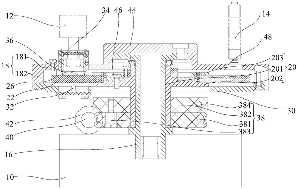
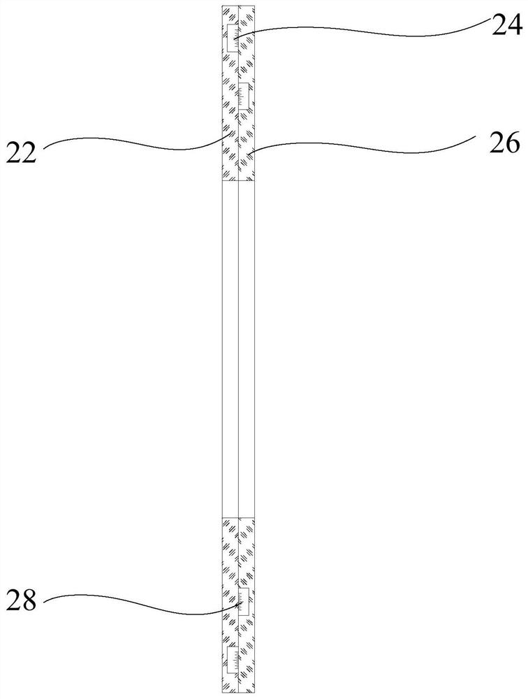
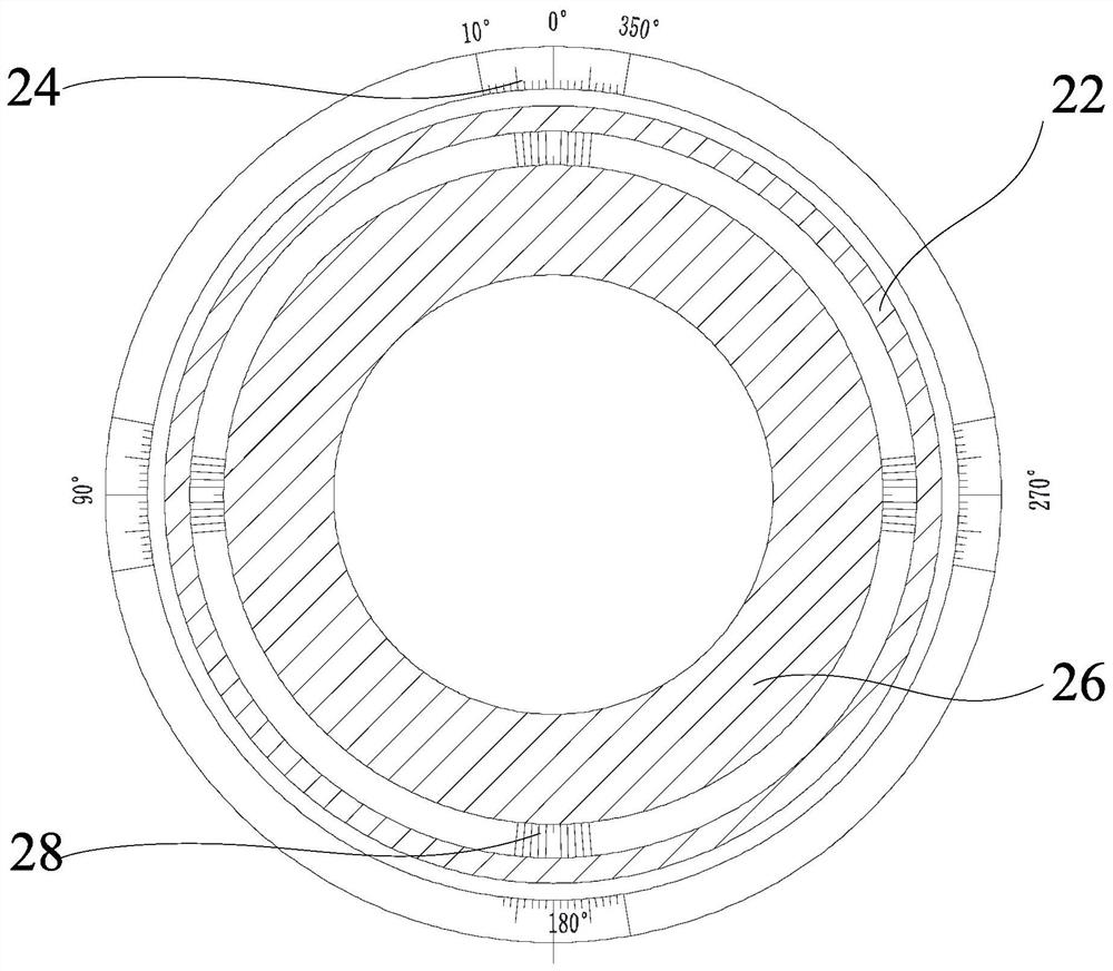
[0036] Refer below Figure 1 to Figure 6 The composite photoelectric encoder device according to some embodiments of the present invention is described.

[0037] In the embodiment of the present in...


PUM


Abstract

The invention provides a composite photoelectric coded disc device, and relates to the technical field of photoelectric coded disc devices. An optical dial and an optical coded disc are glued to forma composite coded disc by using an optical special processing technology so that an outer ring scribed line and an inner ring scribed line are positioned on the inner side of the composite coded discto protect the scribed lines; the storage environment requirements of the optical dial and the photoelectric coded disc are reduced, and the phenomena of mildew and fogging of the photoelectric codeddisc are reduced. The composite coded disc can enable the optical dial and the optical coded disc to rotate coaxially, the technical effect that one disc has multiple purposes is achieved, and opticalsignal output is completed through cooperation of 360 scribed line areas of the outer ring of the composite coded disc, the optical microscopic system and the ocular lens set. Moire fringes are generated through relative movement between 720 scribed line areas of an inner ring of the composite code disc and the indication grating, then received by the photoelectric converter and outputted as sineand cosine electric signals with the phase difference of 90 degrees. Coaxial output of photoelectric signals is achieved so that connecting shaft errors are avoided, and stability of output signals is guaranteed.

Description

technical field [0001] The invention relates to the technical field of photoelectric code disk devices, in particular to a composite photoelectric code disk device. Background technique [0002] At present, in related technologies, the readings of the domestic optical system are composed of a dial plus a display optical microscope system and an eyepiece group, while the electrical system generally uses an encoder to collect rotation signals. In the original system of the equipment, the optical dial signal and the encoder exist separately, and the optical signal and the electrical signal are output separately; resulting in a large connection error between the dial rotation shaft and the encoder shaft, the output signal is unstable, the cost is high, the volume is large, and the installation and debugging are difficult. question. Moreover, the optical dial itself still has the phenomenon of mold and fogging, and there is a problem that the storage environment of the equipment...

Claims


Application Information

Patent Timeline
Patent Type & Authority Applications(China)
IPC IPC(8): G01D5/244G01D5/26
CPCG01D5/244G01D5/264
Inventor 孙毓卿吴占平张明生田径罗中文陈飞
Owner 沈阳第三三零一装备制造有限公司
Why Eureka
Try Eureka