
Power transmission line iron tower tension calculation method

A transmission line iron tower and calculation method technology, applied in calculation, computer-aided design, electrical digital data processing, etc., can solve the problems of inability to accurately calculate the tension difference of towers, etc., and achieve the effects of speed sensitivity, successful calculation, and accurate calculation

Pending Publication Date: 2020-12-18
季龙三
View PDF0 Cites 1 Cited by
  • Summary
  • Abstract
  • Description
  • Claims
  • Application Information

AI Technical Summary

Problems solved by technology

[0003] At present, the method of calculating the tension difference between the front and rear sides of the tower is mainly calculated by the "equal line method" model. This calculation method is only suitable for the calculation of uniform loads in the file, ignoring the influence of the height difference of the tower and wind speed on the calculation results. Influence, resulting in the inability to accurately calculate the tension difference of the tower in actual operation

Method used


Image

  • Power transmission line iron tower tension calculation method
  • Power transmission line iron tower tension calculation method
  • Power transmission line iron tower tension calculation method

Examples


Embodiment Construction

[0043] The following will clearly and completely describe the technical solutions in the embodiments of the present invention with reference to the accompanying drawings in the embodiments of the present invention. Obviously, the described embodiments are only some, not all, embodiments of the present invention. Based on the embodiments of the present invention, all other embodiments obtained by persons of ordinary skill in the art without creative efforts fall within the protection scope of the present invention.

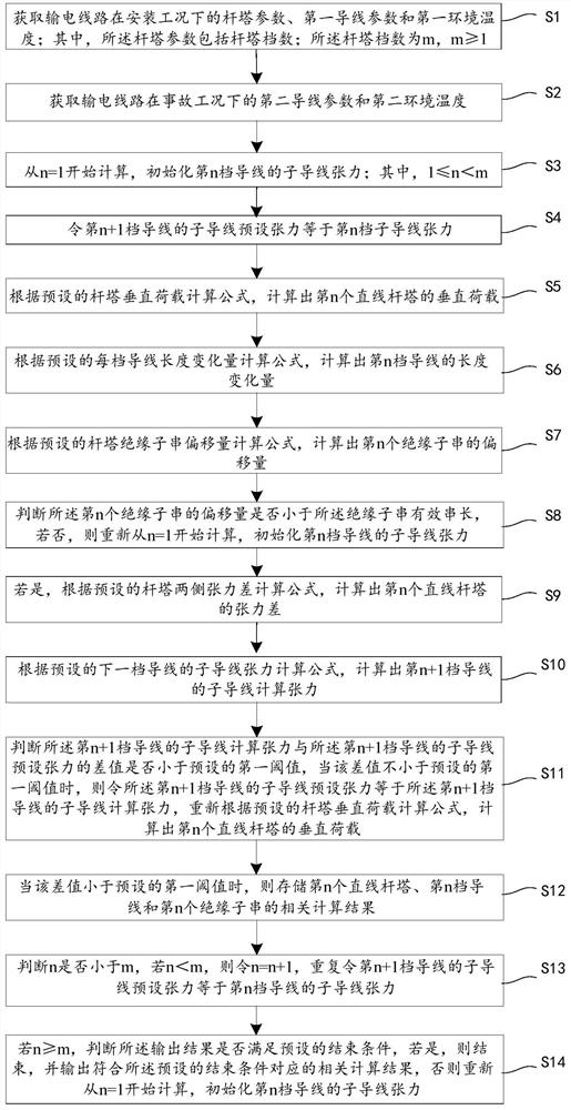
[0044] see figure 1 , is a schematic flow chart of the first embodiment of the method for calculating the tension of the transmission line iron tower provided by the present invention, and the method includes steps S1 to S14:

[0045] S1. Obtain the tower parameters, the first wire parameters and the first ambient temperature of the transmission line under the installation condition; wherein, the tower parameters include the number of tower stalls; the number of to...


PUM


Abstract

The invention discloses a power transmission line iron tower tension calculation method, which comprises the steps of obtaining parameters of a wire under an installation working condition and an accident working condition, and initializing the tension of the nth-gear wire, wherein n is greater than or equal to 1 and less than m, m being the number of gears of a tower; enabling the preset tensionof the (n + 1) th-gear wire to be equal to the tension of the nth-gear wire; calculating the vertical load of the nth tower, the length variation of the nth gear of wire and the offset of the nth insulator string; judging whether the offset is less than the effective string length or not, and if not, performing re-initializing; if yes, calculating the tension difference of the nth tower and the calculated tension of the (n + 1) th gear wire; judging whether the difference between the calculated tension of the (n + 1) th gear of wire and the preset tension is less than a threshold value or not,and if not, performing reinitializing; if yes, storing a calculation result; judging whether n is smaller than m or not, if n is smaller than m, setting n to be equal to n + 1, and repeatedly calculating the tension of the next gear of wire; and if n is greater than or equal to m, judging whether an end condition is met, if so, ending the operation, and otherwise, performing re-initializing. According to the invention, the tension difference of a tower can be measured more accurately.

Description

technical field [0001] The invention relates to the technical field of power transmission lines, in particular to a method for calculating the tension of power transmission line iron towers. Background technique [0002] my country's transmission lines have a high degree of construction and are widely distributed, but transmission lines in different external environments also face different accident risks. Some transmission lines are located in coastal areas, which have been harassed by typhoons all year round and face the risk of wind disaster accidents. Some lines are located in high mountain areas with large undulating terrain, so they face the problems of large gear distances, large height differences, and high suspension points. Other transmission lines in the northwest or southeast regions are affected by ice all year round and face the hidden danger of ice disaster accidents. These accidents will cause disconnection or unbalanced force on the transmission line condu...

Claims


Application Information

Patent Timeline
Patent Type & Authority Applications(China)
IPC IPC(8): G06F30/20G06F119/14G06F119/08G06F113/04G06F111/10
CPCG06F30/20G06F2119/14G06F2119/08G06F2113/04G06F2111/10
Inventor 季龙三
Owner 季龙三
Learn More