Hole Forming Device, Hole Forming Method and Application for Ground Stress Test of Soil Formation

A technology of formation in-situ stress and hole-forming device, which is applied in the fields of on-site foundation soil survey, construction, and infrastructure engineering, etc., can solve the problems of inability to perform rapid in-situ stress test, the influence of test results is also great, and the influence of stress test results, etc. To achieve the effect of simple and reliable test method, accurate numerical calculation results of soil stratum, and high construction safety

Active Publication Date: 2019-03-29
SHIJIAZHUANG TIEDAO UNIV
View PDF5 Cites 0 Cited by
  • Summary
  • Abstract
  • Description
  • Claims
  • Application Information

AI Technical Summary

Problems solved by technology

However, at present, the soil layer is greatly disturbed during the drilling process of the geological exploration hole, which affects the initial ground stress test results.
And after the hole is formed, the in-situ stress test cannot be carried out quickly and without intervals, resulting in a certain release of the in-situ stress in the soil, which has a great impact on the test results

Method used


Image

  • Hole Forming Device, Hole Forming Method and Application for Ground Stress Test of Soil Formation
  • Hole Forming Device, Hole Forming Method and Application for Ground Stress Test of Soil Formation
  • Hole Forming Device, Hole Forming Method and Application for Ground Stress Test of Soil Formation

Examples


Embodiment 1

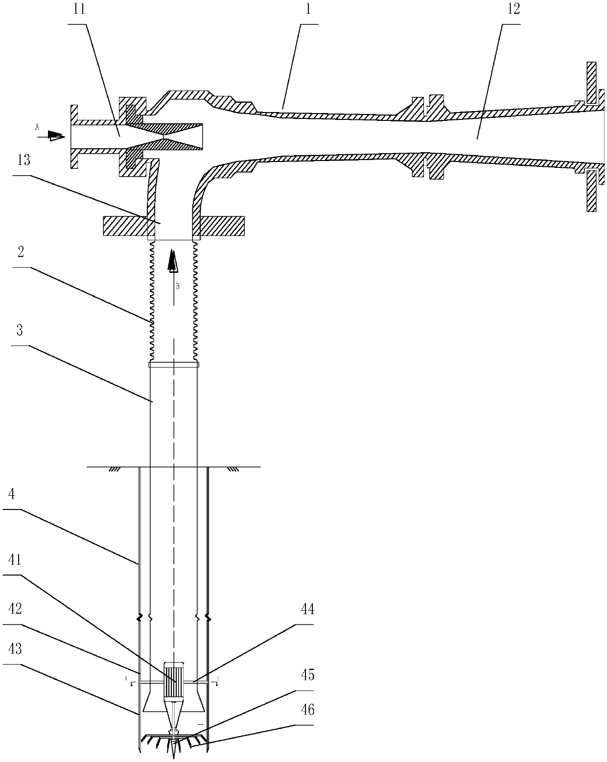
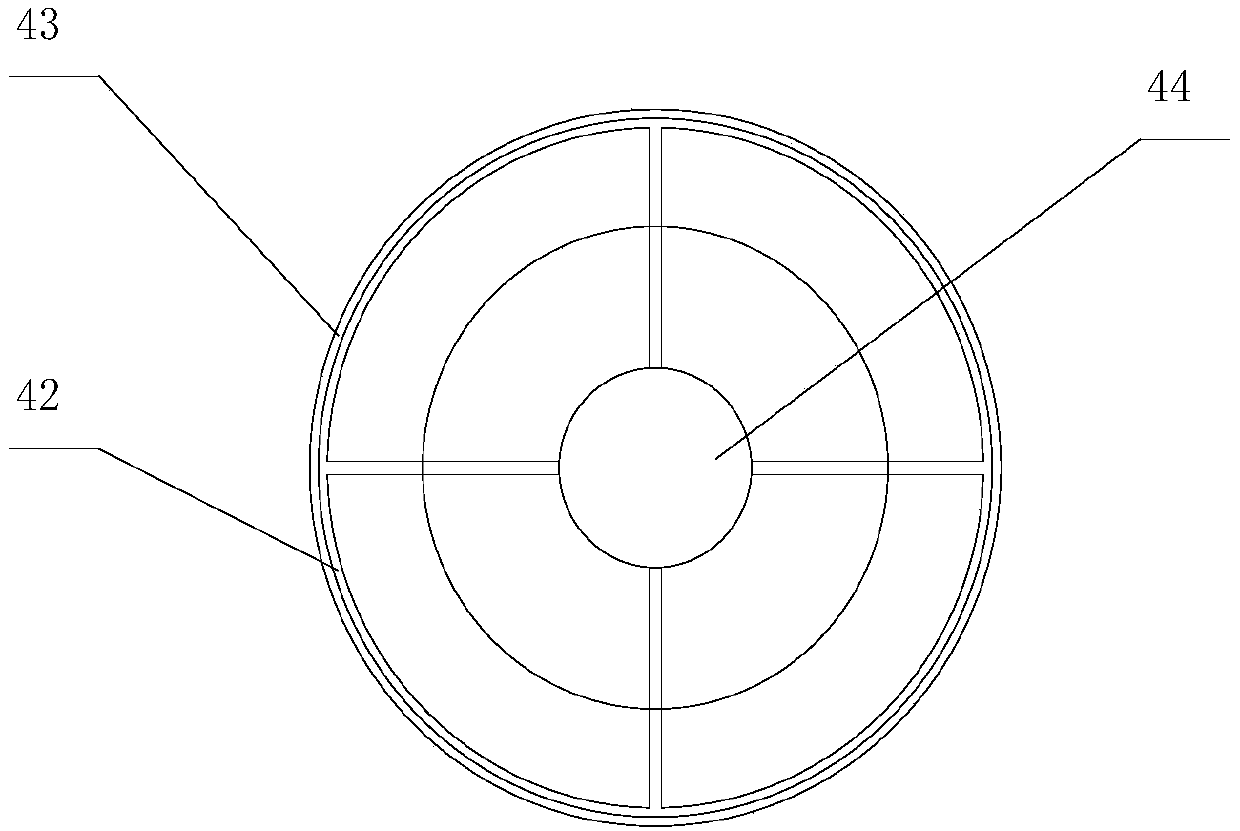
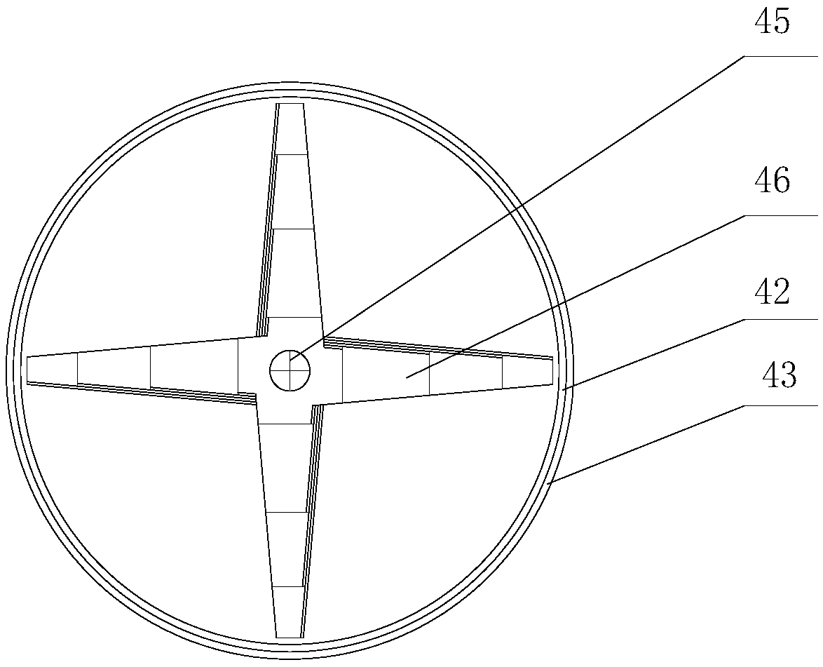
[0045] The hole diameter of present embodiment is 40cm, and the internal diameter of outer layer protective shell 43 is 40cm, and the inner diameter of inner layer protective shell 42 is 39cm, and the blade foot angle of inner and outer layer protective shell 43 is 30 °. The central pyramid cutter 45 adopts a quadrangular pyramid structure, and the U-shaped cutter group is set around the central pyramid cutter 45. It includes 4 U-shaped cutter groups with different spans. The U-shaped cutters arranged in pattern form, the single U-shaped cutter 46 of the first group of U-shaped cutters has a horizontal span of 9cm, the bending angle of the blade is 100°, and the single U-shaped cutter of the second group of U-shaped cutters Type cutter 46 horizontal span is 18cm, the bending angle of blade is 110 °, the single U-shaped cutter 46 horizontal span of the third group of U-shaped cutter group is 27cm, the bending angle of blade is 120 °, the fourth group The single U-shaped cutter ...

Embodiment 2

[0047] The hole diameter of present embodiment is 10cm, and the inner diameter of outer layer protective shell 43 is 10cm, and the inner diameter of inner layer protective shell 42 is 8cm, and the blade foot angle of inner and outer layer protective shell 43 is 24 °. The central pyramid cutter 45 adopts a quadrangular pyramid structure, and the U-shaped cutter group is set around the central pyramid cutter 45. It includes 2 sets of U-shaped cutter groups with different spans. The uniform U-shaped cutters are composed of uniformly distributed U-shaped cutters. The single U-shaped cutter 46 of the first group of U-shaped cutters has a horizontal span of 5cm and the bending angle of the blade is 100°. The single U-shaped cutter of the second U-shaped cutter group Type cutter 46 horizontal spans are 7cm, the bending angle of blade is 120 °, promptly the cutting diameter of first U-shaped cutter group is 5cm, and the cutting diameter of second U-shaped cutter group is 7cm.


PUM


Abstract

The invention relates to a pore-exploration and pore-forming device and method for soil stratum ground stress testing and application of the pore-exploration and pore-forming device and method. The pore-forming device comprises a negative pressure soil pumping mechanism, a soil pumping pipe and a soil cutting mechanism, wherein the soil cutting mechanism communicates with the negative pressure soil pumping mechanism through the soil pumping pipe, and soil cut by the soil cutting mechanism is pumped and then discharged by means of negative pressure difference of the negative pressure soil pumping mechanism. According to the pore-exploration and pore-forming device and method for soil stratum ground stress testing and the application of the pore-exploration and pore-forming device and method, steel shells are adopted for wall retaining, a specially made cutter is adopted for cutting soil, pores can be formed quickly through a geological pore-exploration and pore-forming technology of pumping soil through negative pressure, the disturbance on stratums is small, the pore diameter range can be adjusted, the construction cost is low, the construction safety is high, operation is easy andconvenient, and the pore-exploration and pore-forming device and method are suitable for unsaturated sandy soil (such as medium sand, fine sand and mealy sand) with the moisture content lower than 40% and unsaturated soil stratums (such as silt, silty clay and loess) with the moisture content lower than 50%. In addition, a soil stratum ground stress testing method provided by the invention is simple and reliable, can detect out initial ground stress, has great significance on numerical calculation of the soil stratums, and ensures that soil stratum numerical calculation results are more accurate and comprehensive.

Description

technical field [0001] The invention belongs to the technical field of geological prospecting hole forming, and in particular relates to a hole forming device for testing the ground stress of soil strata, a hole forming method and its application. Background technique [0002] In-situ stress refers to the stress existing in rock and soil, which can be divided into self-gravity stress and structural stress. The determination of initial ground stress is very important for foundation engineering and underground engineering. However, at present, in-situ stress tests are generally carried out after the excavation of foundation pits or caverns is exposed, and there are few ways to accurately obtain in-situ stress in the soil layer in advance. For rock mass structure, there are three methods of in-situ stress testing: stress relief method, stress recovery method and hydraulic fracturing method. Among them, the first two methods are suitable for exposed rock mass, while the latter...

Claims


Application Information

Patent Timeline
Patent Type & Authority Patents(China)
IPC IPC(8): E02D1/02
Inventor 胡指南任宇铮党丁宾胜林王树永马超超冯怀平杨万精赵子锋赵晓晓黄继新吴树清
Owner SHIJIAZHUANG TIEDAO UNIV
Why Eureka
Try Eureka