Supercharge Your Innovation With Domain-Expert AI Agents!

Novel single-stage isolating switch

An isolation switch, single-stage technology, used in electrical switches, air switch parts, contacts, etc., can solve problems affecting structural stability, prone to failure, corrosion of parts, etc., to increase stability and safety, external structure Simple, space-saving effects

Pending Publication Date: 2020-12-18
山东广域科技有限责任公司
View PDF1 Cites 0 Cited by
  • Summary
  • Abstract
  • Description
  • Claims
  • Application Information

AI Technical Summary

Problems solved by technology

During the overhaul and defect handling of the isolating switch, the faults of the isolating switch generally include: corrosion of components, heating of connections, oxidation of the main body, shedding of mechanisms, etc. Safe and stable operation of power lines
In order to avoid the loss caused by line tripping due to the failure of the isolating switch to the user, research and improve the device components in the parts where the isolating switch is prone to failure, select high-quality materials, carry out reasonable and compliant design, process and manufacture a new type of single Level isolating switch to ensure that no line tripping accidents occur due to isolating switch
[0004] For example, the invention with application number 201520690267.8 discloses a new type of GW9 isolating switch. The hook structure is formed by hook plate, clamp plate, torsion spring and limit plate structure to realize the hook lock function. The structure is exposed to the outside air and is easily weathered. Corrosion, which affects structural stability and is prone to failure

Method used


Image

  • Novel single-stage isolating switch
  • Novel single-stage isolating switch
  • Novel single-stage isolating switch

Examples


Embodiment 1

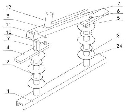
[0026] refer to figure 1 As shown, a new type of single-stage isolating switch includes a base plate 1, an insulating support column A2 and an insulating support column B3 vertically fixed at both ends of the base plate 1, and wirings fixedly connected to the tops of the insulating support column A2 and the insulating support column B3 respectively. Board A4 and wiring board B5, contact A7 and contact B9 fixedly connected to wiring board A4 and wiring board B5 respectively, pin shaft 6 connected to the top of contact B9, and pin shaft 6 are rotatably connected to contact A7 The contact-connected knife switch 8 and the pin shaft 6 are provided with a torsion spring, and the two ends of the torsion spring are fixedly connected with the contact B9 and the knife switch 8 respectively;

[0027] The end of terminal board A4 close to terminal board B5 is provided with a lower lock tube 10, and the lower surface of the knife switch 8 is fixed with an upper lock tube 11 at the position...

Embodiment 2

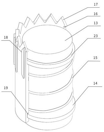
[0030] refer to figure 1 , figure 2 , image 3 , Figure 4 and Figure 5 As shown, the lower lock tube 10 includes a connecting column 13 fixed to the wiring board A4, an elastic component sleeved on the connecting column 13 and a lower locking tube 16 sleeved on the elastic component. The upper fixed ring 23, the movable ring 14 sleeved on the connecting column 13 and the spring 15 connecting the fixed ring 23 and the movable ring 14;

[0031] The inside of the lower locking tube 16 is provided with a fixed groove 19 matching the movable ring 14, the top of the lower locking tube 16 is provided with a triangular tooth plate 17 along the circumferential direction, and the outer surface of the upper part of the lower locking tube 16 protrudes along the circumferential direction. There is a lower block 18;

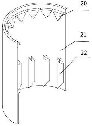
[0032] The upper locking tube 11 includes an upper locking tube 21 fixedly connected to the knife switch 8, the upper inner surface of the upper locking tube 21 protru...


PUM


Abstract

The invention discloses a novel single-stage isolating switch, which relates to the field of power equipment, and comprises a bottom plate, an insulating support column A and an insulating support column B vertically fixed at two ends of the bottom plate, a wiring board A and a wiring board B respectively and fixedly connected to the top ends of the insulating support column A and the insulating support column B, a contact A and a contact B respectively and fixedly connected to the wiring board A and the wiring board B, a pin shaft connected to the top end of the contact B, and a disconnectinglink rotationally connected with the pin shaft and in contact connection with the contact A. The pin shaft is sleeved with a torsion spring, and the two ends of the torsion spring are fixedly connected with the contact B and the disconnecting link respectively; a lower locking pipe is arranged at the end, close to the wiring board B, of the wiring board A, an upper locking pipe is fixed to the position, corresponding to the lower locking pipe, of the lower surface of the disconnecting link, the lower locking pipe is sleeved with the upper locking pipe to form a pressing rotary locking structure, a handle is arranged on the upper surface of the disconnecting link, and operation is easy, stable and reliable.

Description

technical field [0001] The invention relates to power system application equipment, in particular to a novel single-stage isolating switch. Background technique [0002] The isolation switch is a switching device mainly used for isolating power supply, switching operation, connecting and cutting off small current circuits, and has no arc extinguishing function. When the isolating switch is in the off position, there is an insulation distance between the contacts that meets the specified requirements and an obvious disconnection mark; when it is in the close position, it is a switchgear that can carry the current under normal circuit conditions and the current under abnormal conditions within a specified time . It is generally used as a high-voltage disconnector, that is, a disconnector with a rated voltage above 1kV. Its working principle and structure are relatively simple, but due to the large amount of use and high requirements for working reliability, it is very importa...

Claims


Application Information

Patent Timeline
IPC IPC(8): H01H31/02H01H1/50H01H21/56
CPCH01H1/50H01H21/56H01H31/02H01H31/023
Inventor 李志宏孙双春闵锐喻萍李晓晨方宁张文政马新功杨艳李晓鹏王同波
Owner 山东广域科技有限责任公司
Features
  • R&D
  • Intellectual Property
  • Life Sciences
  • Materials
  • Tech Scout
  • Unparalleled Data Quality
  • Higher Quality Content
  • 60% Fewer Hallucinations
Learn More