Eureka AIR delivers breakthrough ideas for toughest innovation challenges, trusted by R&D personnel around the world.

Well bottom shearing foam maker for foam combination flooding

A foamer and foam technology, applied in mixers, mixing methods, wellbore/well components, etc., can solve problems such as defoaming and foam breaking that cannot be overcome, and achieve convenient use and operation, enhanced recovery, and operation simple effect

Active Publication Date: 2020-12-22
PETROCHINA CO LTD +1
View PDF8 Cites 0 Cited by
  • Summary
  • Abstract
  • Description
  • Claims
  • Application Information

AI Technical Summary

Problems solved by technology

[0005] The technical problem to be solved by the present invention is to overcome the existing micro-foam injection process existing in the background technology. At present, there is no reliable and effective method that cannot overcome the unfavorable factors of foam defoaming and foam breaking in the pipeline wellbore during foam injection, thereby affecting foam injection. In order to solve the problem of quality, a bottom hole shear foamer for composite foam flooding is provided. The bottom hole shear foamer for foam composite flooding can greatly improve the quality of shear foam injection, so that the foam injection into the formation is uniform, Avoid the ineffective circulation of gas, so that a large amount of foam can be evenly dispersed in the formation, greatly reducing the unfavorable factors of foam defoaming and foam breaking, and providing technical support for foam composite flooding to reduce costs and greatly increase recovery

Method used


Image

  • Well bottom shearing foam maker for foam combination flooding
  • Well bottom shearing foam maker for foam combination flooding
  • Well bottom shearing foam maker for foam combination flooding

Examples


Embodiment Construction

[0016] The present invention will be further described below in conjunction with accompanying drawing:

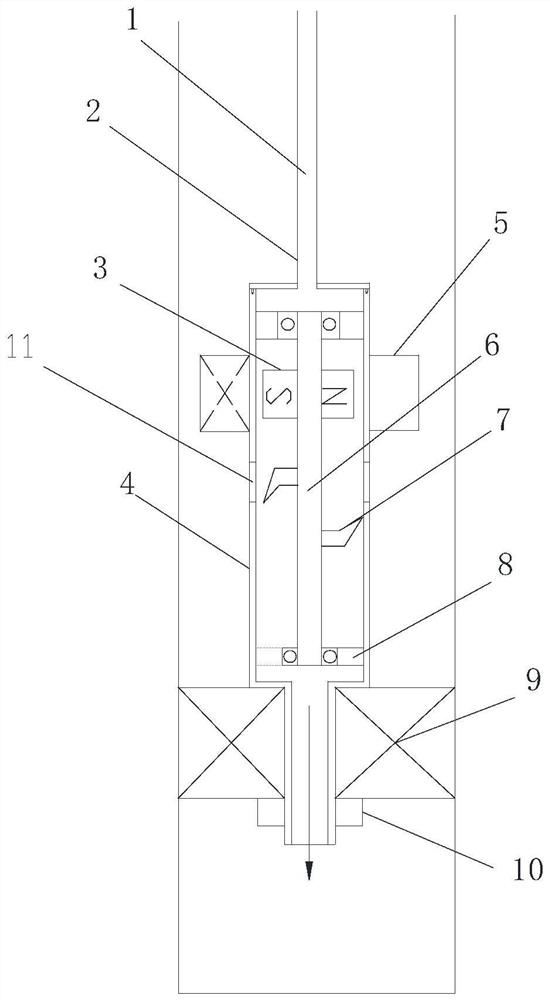
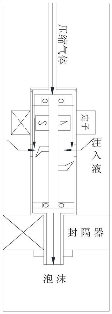
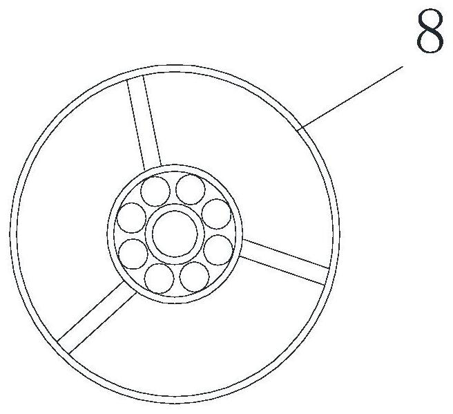
[0017] as attached figure 1 As shown, a bottom hole shearing foamer for foam composite flooding includes a shearing foamer 4, the upper and lower parts of the shearing foamer 4 are two circular steel drum shells with different diameters, and the upper circular steel The diameter of the barrel shell is larger than the diameter of the lower circular steel barrel; the upper and lower ends of the upper steel barrel shell are respectively provided with an inlet end cover and a lower outlet, and the inlet end cover of the shear foamer 4 and the inlet pipeline 2 are threaded Connected, the compressed gas 1 is passed into the intake pipeline; the upper part of the outlet of the lower part of the shear foamer 4 is fixed with a bearing support frame 8, and the center hole of the bearing support frame 8 is fixedly connected to the bearing 6, such as image 3 As shown, several connect...


PUM


Abstract

The invention relates to a well bottom shearing foam maker for foam combination flooding. The invention mainly aims to overcome the problems that a reliable and effective mine field injection method for an existing micro-foam injection process has not been reported at present, and foam injection quality is affected since the adverse factors of defoaming and foam breaking of foam in a pipeline shaft during foam injection cannot be overcome. The shearing foam maker is characterized in that a bearing support frame is fixed at a lower outlet of the shearing foam maker, and a bearing is fixedly connected to a central hole of the bearing support frame; the upper and lower ends of the bearing are respectively provided with a permanent-magnet rotor and a plurality of shearing blades; a packer is arranged outside a round steel drum at the lower part of the shearing foam maker; a permanent magnet motor stator is fixed on the part, located at the upper part of the shearing foam maker, of the round steel drum shell and corresponds to the internal permanent magnet rotor; and a plurality of holes are formed in the middle part of a shearing foam maker shell in a circumferential direction. According to the well bottom shearing foam maker for foam combination flooding, shearing foam injection quality can be greatly improved, more generated foam can be directly injected into a stratum, and adverse factors of foam defoaming and foam breaking are greatly reduced.

Description

technical field [0001] The invention relates to the technical field of enhanced oil recovery for tertiary oil recovery in oilfield development engineering, in particular to a bottom-hole shear foamer for foam composite flooding. Background technique [0002] Foam flooding is an important technology for water plugging and profile control to enhance oil recovery, which has the ability to expand macroscopic swept volume and improve microscopic oil displacement efficiency. The traditional foam flooding method of gas-liquid alternating injection can achieve the effect only when the amount of gas injected is very small. If there is too much gas, it will cause serious gas channeling, and the injection-production system will be greatly affected by the gas-liquid alternation. Switching Sometimes a large amount of liquid will enter the large compressor, causing damage to the compressor. The cost of the large compressor is very high, and once it is damaged, the injection will fail. In...

Claims


Application Information

Patent Timeline
IPC IPC(8): B01F7/04B01F3/04E21B43/16
CPCE21B43/16B01F23/2351B01F27/70
Inventor 李星侯兆伟王银
Owner PETROCHINA CO LTD
Why Eureka
Eureka Blog
Learn More