
Electronic positioning roller shearing machine

A technology of electronic positioning and rolling shears, which is applied in the direction of shearing devices, shearing machine equipment, shearing machine accessories, etc., can solve the problems of tab deformation, grid deformation, grid strength reduction, etc., to reduce deformation , High cutting efficiency, and the effect of improving cutting accuracy

Active Publication Date: 2020-12-22
中国船舶重工集团衡远科技有限公司
View PDF7 Cites 0 Cited by
  • Summary
  • Abstract
  • Description
  • Claims
  • Application Information

AI Technical Summary

Problems solved by technology

[0002]With the rapid development of the lead-acid battery industry, the continuous production, high efficiency, and thin grid of the battery grid have become a trend, and the continuous grid On-line slitting basically adopts mechanical positioning. The principle of mechanical positioning is to rely on the self-weight of the grid and the positioning hook device on the equipment to cooperate with the grid ear. However, after the grid is thinner, the strength of the grid is greatly reduced. In addition, after the lead paste is applied, the weight of the lead paste presses down on the grid. During the continuous positioning process, the tabs where the grid is hung will bear continuous impact and also bear the force of the lead paste pressing down on the grid. It is easy to cause tab deformation and grid deformation

Method used


Image

  • Electronic positioning roller shearing machine
  • Electronic positioning roller shearing machine
  • Electronic positioning roller shearing machine

Examples


Embodiment Construction

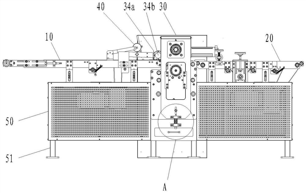
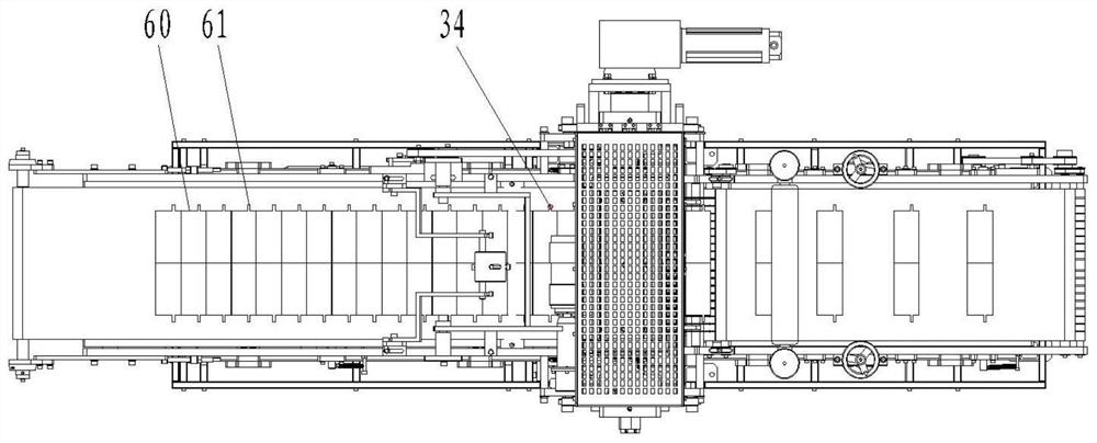
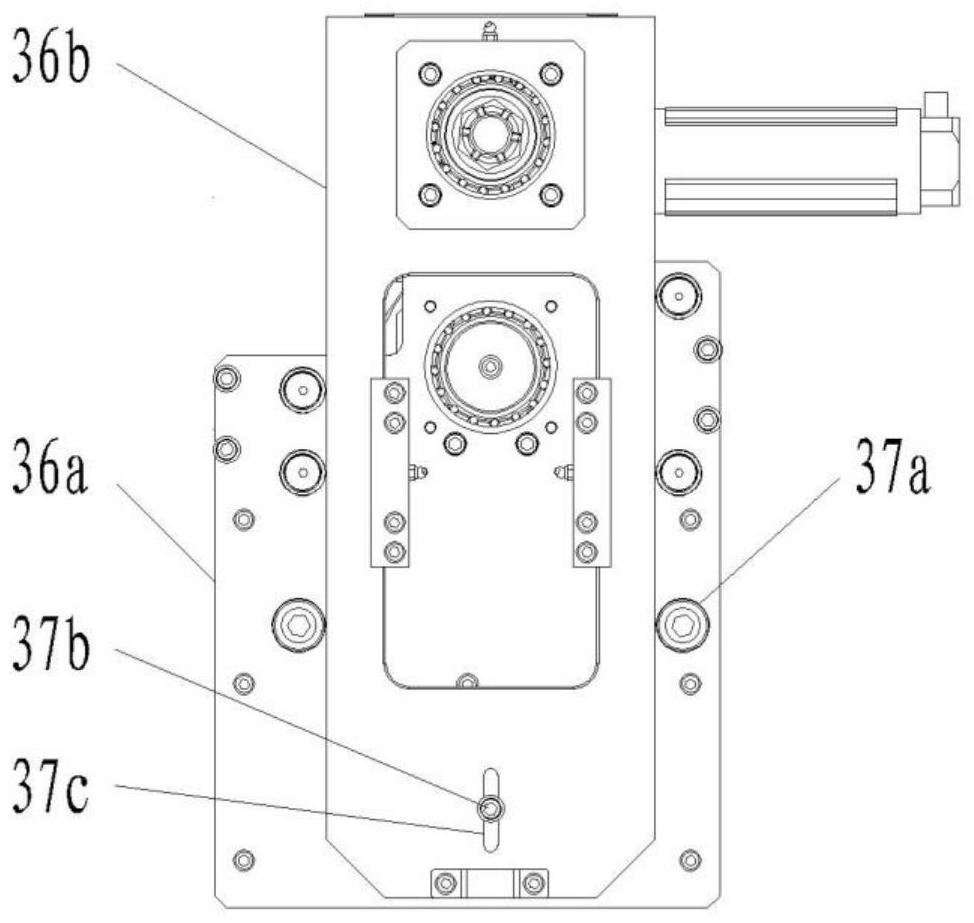
[0024] The electronic positioning rolling shearing machine of the present embodiment comprises a front conveyor belt 10 and a rear conveyor belt 20 which are arranged flush and transported in the same direction, and a rolling cutting device 30 installed between the front conveyor belt and the rear conveyor belt. The device comprises a hob frame, a lower roller 31 and an upper roller 32 which are rotatably mounted on the hob frame and a positioning sensor. It is also installed on the hob frame in a manner that can adjust the center distance vertically. The outer circumference of the upper roller 32 is evenly distributed with a plurality of cutters 33 to cooperate with the lower roller to realize shearing of the grid. The positioning sensor includes a The tab position sensor 34a for detecting the position of the tab, the speed sensor 34b for detecting the transport speed of the grid, and the cutter position sensor 34c for detecting the position of a certain cutter. The flush set...


PUM


Abstract

The invention discloses an electronic positioning roller shearing machine which comprises a front conveying belt, a rear conveying belt and a roller cutting device installed between the front conveying belt and the rear conveying belt. The roller cutting device comprises a hob head, a lower roller, an upper roller and a positioning sensor, wherein the lower roller and the upper roller are rotatably installed on the hob head; and a plurality of cutters are evenly distributed in the outer circumference direction of the upper roller. The positioning sensor comprises a position sensor used for detecting the positions of polar lugs, a speed sensor used for detecting the conveying speed of grids and a cutter position sensor used for detecting the position of a certain cutter. In the slitting process of the electronic positioning roller shearing machine, the continuous grids are flatly laid on the front conveying belt, are slit without participation of gravity, are conveyed at a relatively constant speed under the action of the front conveying belt and cannot deform due to gravity; and in addition, the sensors are used for positioning the continuous grids to achieve cutting, mechanical contact with the continuous grids does not exist in the process, and deformation of grid strips in the shearing process is reduced.

Description

technical field [0001] The invention relates to the technical field of lead-acid batteries, in particular to an electronic positioning rolling shear. Background technique [0002] With the rapid development of the lead-acid battery industry, the continuous production of battery grids, high efficiency, and thin grids have become a trend, and the online slitting of continuous grids basically adopts mechanical positioning. The principle of mechanical positioning is The grid is positioned by the self-weight of the grid plus the positioning hook device on the equipment and the grid ear. However, after the grid is thinned, the strength of the grid is greatly reduced. In addition, after the lead paste is applied, the weight of the lead paste presses down on the grid. , during the continuous positioning process, the tabs where the grid is hung will bear continuous impact, and also bear the force of the grid that is pressed down by the lead plaster, which can easily cause tab deforma...

Claims


Application Information

Patent Timeline
IPC IPC(8): B23D31/00B23D33/00
CPCB23D31/00B23D33/00Y02E60/10
Inventor 熊金磊冯军魏治千王菊艳
Owner 中国船舶重工集团衡远科技有限公司
Learn More