
Self-supporting friction stir welding device and welding method thereof

A welding device and friction stir technology, applied in welding equipment, non-electric welding equipment, metal processing equipment, etc., can solve the problems of short service life, unstable welding process, high use cost, etc., and achieve good manufacturability and versatility, guarantee Welding quality and the effect of reducing production cost

Pending Publication Date: 2020-12-22
HARBIN INST OF TECH AT WEIHAI +1
View PDF8 Cites 1 Cited by
  • Summary
  • Abstract
  • Description
  • Claims
  • Application Information

AI Technical Summary

Problems solved by technology

[0005] (1) Using two stirring needles, the installation is complicated and it is difficult to achieve a high coaxiality
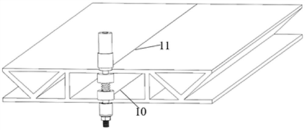
(2) Hollow profiles with a length of tens of meters can not avoid the fluctuation of the inner cavity height of the assembled box structure to be welded, and the load-bearing upper and lower shoulders cannot adapt to the hollow in the direction perpendicular to the surface of the hollow profile during the welding process. The fluctuation of the inner cavity height of the box-shaped structure to be welded by the profile assembly is likely to cause the upper and lower shoulders of the bearing to be out of contact with the inner cavity surface of the box-shaped structure to be welded or the press-in amount is too large, which makes the welding process unstable and the stirring needle breaks
(3) During the welding process, the upper shoulder, the load-bearing upper and lower shoulders and the lower shoulder rotate at the same time, which requires a large motor power and a large welding torque, the stirring needle is easy to break, and the service life is short; the high welding heat input leads to coarsening of the grain , the precipitate phase dissolves, and the mechanical properties of the joint decrease
(4) It is difficult to disassemble the stirring head, and the severe vibration during the welding process may easily cause the thread to be stuck, resulting in that the stirring needle or the shaft shoulder cannot be replaced when it is damaged, and the use cost is high

Method used


Image

  • Self-supporting friction stir welding device and welding method thereof
  • Self-supporting friction stir welding device and welding method thereof
  • Self-supporting friction stir welding device and welding method thereof

Examples


Embodiment Construction

[0028] The present invention can be better understood from the following examples. However, those skilled in the art can easily understand that the content described in the embodiments is only for illustrating the present invention, and should not and will not limit the present invention described in the claims. The specific implementation manner of the present invention will be described below in conjunction with the accompanying drawings.

[0029] In the description of the present invention, it should be understood that the orientation or positional relationship indicated by the terms "upper", "lower", "top", "bottom", "inner" etc. is based on the orientation or positional relationship shown in the drawings , is only for the convenience of describing the present invention and simplifying the description, but does not indicate or imply that the device or element referred to must have a specific orientation, be constructed and operated in a specific orientation, and thus shoul...


PUM


Abstract

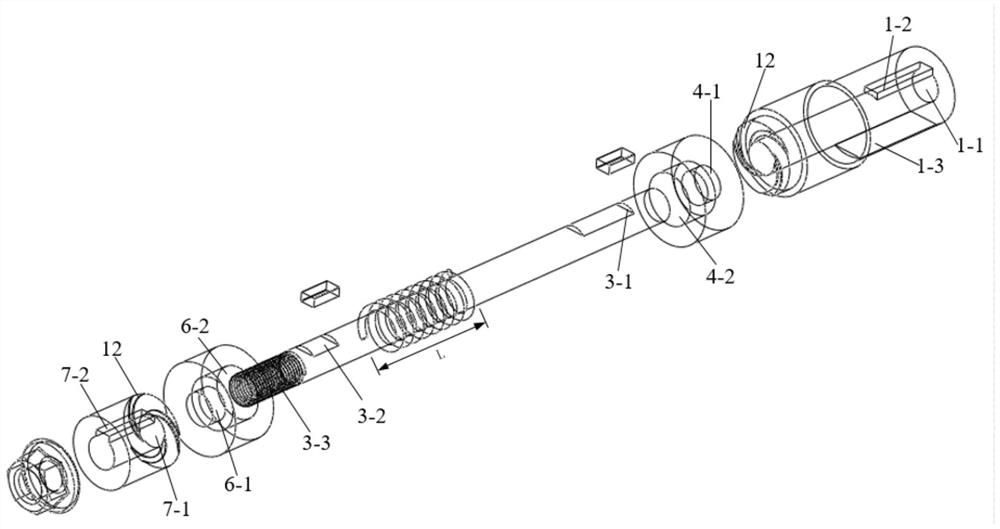
The invention relates to a self-supporting friction stir welding device and a welding method thereof. The device solves the problem that a box-shaped structure to be welded formed by assembling hollowprofiles needs double-sided friction stir welding. The device is provided with a stirring needle, wherein the stirring needle sequentially penetrates an upper shaft shoulder, a first middle shaft shoulder, a spring, a second middle shaft shoulder and a lower shaft shoulder, a first counter bore is formed in the lower end of the first middle shaft shoulder, a second counter bore is formed in the upper end of the second middle shaft shoulder, one end of the spring stretches into the first counter bore and makes contact with the upper end face of the first counter bore, the other end of the spring stretches into the second counter bore and makes contact with the lower end face of the second counter bore, the upper shaft shoulder is provided with an upper position key groove, the lower shaftshoulder is provided with a lower position key groove, upper position keys are arranged in an upper end key groove and the upper position key groove, and lower keys are arranged in a lower end key groove and the lower position key groove. According to the device, a distance between the first middle shaft shoulder and the second middle shaft shoulder can be automatically adjusted according to fluctuation of heights of inner cavities of the hollow profiles, and good manufacturability and universality are achieved.

Description

technical field [0001] The invention relates to the field of welding technology, in particular to a self-supporting friction stir welding device and a welding method thereof. Background technique [0002] Friction stir welding is a new type of solid-phase welding technology, which can avoid defects such as pores, thermal cracks, and slag inclusions during the welding process, and can also avoid the burning of alloy elements. Therefore, it has a wide range of applications in the field of welding non-ferrous metals such as aluminum and magnesium. application prospects. During the friction stir welding process, the stirring head is rotated and inserted into the workpiece to be welded, and kept in contact with the workpiece to be welded with a certain pressure, resulting in a large downward force applied to the workpiece to be welded during the welding process. Therefore, during friction stir welding, it is necessary to place a support on the back of the workpiece to be welded....

Claims


Application Information

Patent Timeline
Patent Type & Authority Applications(China)
IPC IPC(8): B23K20/12
CPCB23K20/1245B23K20/126
Inventor 周利李高辉张海峰王苹刘杉梁涛张欣盟
Owner HARBIN INST OF TECH AT WEIHAI
Learn More