Correction mechanism and method for rubber ring annular hole

A correction mechanism and apron technology, applied in metal processing, metal processing equipment, manufacturing tools, etc., can solve the problems that the sealing ring affects the sealing performance of the bearing, the automatic assembly of the steel ball cannot be completed, and the life of the bearing is affected, so as to ensure the smooth detection , avoid rotation, adjust the effect of precision

Pending Publication Date: 2020-12-22
JINAN FIRST MACHINE TOOL GROUP
View PDF0 Cites 3 Cited by
  • Summary
  • Abstract
  • Description
  • Claims
  • Application Information

AI Technical Summary

Problems solved by technology

The apron is a commonly used part in the bearing assembly structure. The quality of the assembly of the sealing ring will directly affect the sealing performance of the bearing, or it will affect the service life of the bearing.
[0003] The traditional way is through manual assembly, which is costly and inefficient
To realize automatic assembly through equipment, the problem of alignment between the ring hole of the rubber ring and the ring hole of the mold must be solved first. Due to the small diameter of the ring hole of the rubber ring, it is difficult to achieve alignment correction between the hole diameter of 2mm and the matching mold hole, resulting in the subsequent steel balls Unable to complete auto-assembly

Method used


Image

  • Correction mechanism and method for rubber ring annular hole
  • Correction mechanism and method for rubber ring annular hole
  • Correction mechanism and method for rubber ring annular hole

Examples


Embodiment Construction

[0033]The technical solutions in the embodiments of the present invention will be clearly and completely described below in conjunction with the accompanying drawings in the embodiments of the present invention. Obviously, the described embodiments are only a part of the embodiments of the present invention, rather than all the embodiments. Based on the embodiments of the present invention, all other embodiments obtained by those of ordinary skill in the art without creative work shall fall within the protection scope of the present invention.

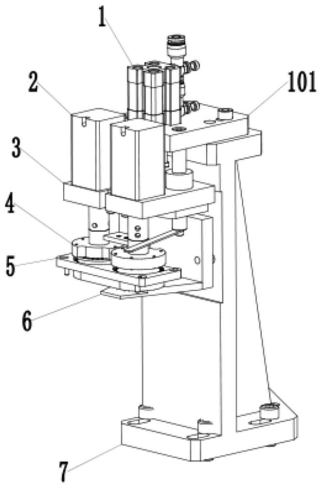
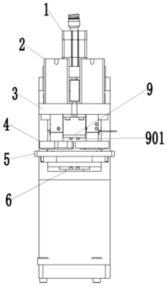
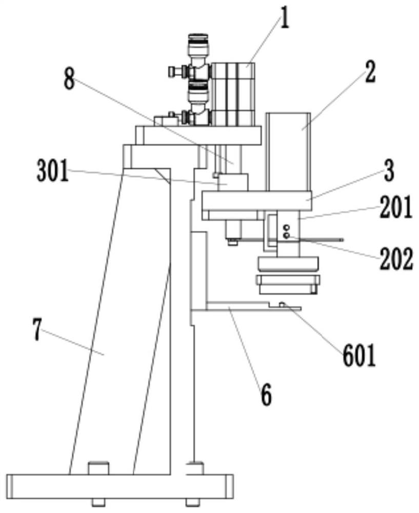
[0034]Such asFigure 1-3 As shown, an apron ring hole correction mechanism includes a positioning cylinder 1, a stepping motor 2, a positioning platen 4, a mold 5, a support base 7 and a through-beam photoelectric switch. The positioning cylinder 1 is fixed on the support base 7 At the upper end, the piston rod of the positioning cylinder 1 is connected with a lifting plate 3, the upper end of the lifting plate 3 is provided with a stepping moto...


PUM


Abstract

The invention discloses a correction mechanism and method for a rubber ring annular hole. The correction mechanism comprises a positioning air cylinder, a stepping motor, a positioning pressing disc,a die, a supporting seat and a correlation type photoelectric switch. The positioning air cylinder is fixed to the upper end of the supporting seat, a lifting plate is connected to a piston rod of thepositioning air cylinder, the stepping motor is arranged at the upper end of the lifting plate, and the positioning pressing disc connected with an output shaft of the stepping motor is arranged on the lower part of the lifting plate. The die is arranged below the positioning pressing disc, a mounting groove for mounting a rubber ring is formed in the upper end of the die, and a die annular holecorresponding to the rubber ring annular hole is formed in the mounting groove. The correlation type photoelectric switch comprises an emitter and a receiver, the emitter and the receiver are correspondingly located on the two sides of the die, and light between the emitter and the receiver penetrates through the die annular hole. Optical fiber detection is adopted, a detection result is accurate,the problem that the rubber ring annular hole and the die annular hole are difficult to align is solved, automatic alignment of hole sites is achieved, and the requirement for automatic bead installation is met.

Description

Technical field[0001]The invention relates to the technical field of bearing assembly equipment, in particular to a correction mechanism and method for an apron ring hole.Background technique[0002]Plastic rubber ring bearings are widely used in drill chuck power tools. They are vulnerable consumables and are in great demand. The rubber ring is a commonly used part in the assembly structure of the bearing. The assembly quality of the seal ring will directly affect the sealing performance of the bearing, or affect the life of the bearing.[0003]The traditional method is manual assembly, which has high cost and low efficiency. To realize automatic assembly through equipment, the problem of alignment between the apron ring hole and the mold ring hole must first be solved. Due to the small diameter of the apron ring hole, it is difficult to achieve alignment correction with a 2mm diameter and a matching mold hole, resulting in subsequent steel balls Unable to complete automatic assembly.S...

Claims


Application Information

Patent Timeline
Patent Type & Authority Applications(China)
IPC IPC(8): B23P19/10
CPCB23P19/10
Inventor 唐连续
Owner JINAN FIRST MACHINE TOOL GROUP
Why Eureka
Try Eureka