Environment-friendly kitchen waste treatment device with solid-liquid separation function

A kitchen waste and solid-liquid separation technology, which is applied in grain processing, manufacturing tools, engine sealing, etc., can solve the problem of poor solid-liquid separation effect, affecting users' experience of using waste disposal devices, and affecting users' follow-up treatment of waste, etc. problems, to achieve the effect of improving user experience, good solid-liquid separation function, and rich functions

Inactive Publication Date: 2020-12-22
刘亚玲
View PDF1 Cites 2 Cited by
  • Summary
  • Abstract
  • Description
  • Claims
  • Application Information

AI Technical Summary

Problems solved by technology

[0004] However, due to the relatively simple structure of the garbage disposal device, the solid-liquid separation effect of the disposal device is poor, which affects the user's subsequent treatment of the garbage, thereby affecting the user's experience of using the garbage disposal device

Method used


Image

  • Environment-friendly kitchen waste treatment device with solid-liquid separation function
  • Environment-friendly kitchen waste treatment device with solid-liquid separation function
  • Environment-friendly kitchen waste treatment device with solid-liquid separation function

Examples


Embodiment 1

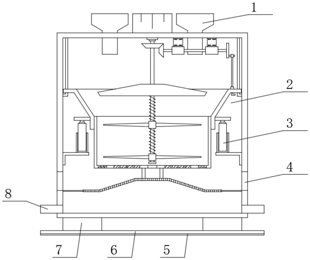
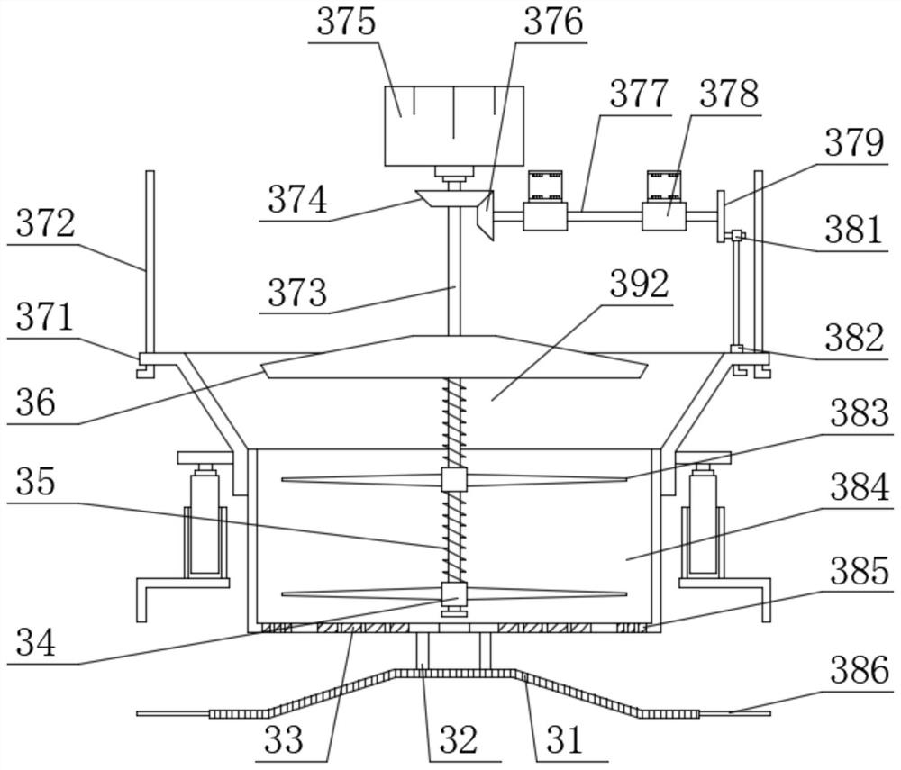
[0023] see Figure 1-Figure 3 , the present invention provides a technical solution: an environment-friendly kitchen waste treatment device with solid-liquid separation function, comprising a crushing box 2, the two ends of the upper surface of the crushing box 2 are fixed with a feeding hopper 1 by welding, the crushing box The bottom end of 2 is welded with drain pipe 8, and the inside of crushing box 2 is provided with crushing mechanism 3, and crushing mechanism 3 comprises driving motor 375, and driving motor 375 is fixedly connected with crushing box 2 by bolt, and the output end of driving motor 375 is welded The transmission square shaft 373 is fixedly connected with the transmission square shaft 373, the top of the transmission square shaft 373 is fixedly connected with the extrusion plate 36 by welding, the bottom end of the transmission square shaft 373 is slidingly connected with the first limit sliding sleeve 34, and the first limit sliding sleeve The two sides of...

Embodiment 2

[0032] On the basis of Embodiment 1, in order to make the shock absorption effect of the garbage disposal device better, in this embodiment, preferably, the two ends of the lower surface of the crushing box 2 are provided with rubber support blocks 7, and the rubber support blocks 7 have a rectangular parallelepiped structure. , the rubber support block 7 is connected with the crushing box 2 by glue bonding, and is supported and shock-absorbed by the rubber support block 7 during use;

[0033] In order to make the use of the garbage disposal device more reliable, in the present embodiment, preferably, the bottom of the crushing box 2 is provided with a support base plate 6, the support base plate 6 is a cuboid structure, and the support base plate 6 and the rubber support block 7 are fixedly connected by screws. At the same time, the support base plate 6 plays a supporting role, so that the use of the garbage disposal device is more reliable;

[0034] In order to make the anti...


PUM


Abstract

The invention discloses an environment-friendly kitchen waste treatment device with a solid-liquid separation function, and belongs to the technical field of environmental protection. The environment-friendly kitchen waste treatment device comprises a crushing box, feeding hoppers are arranged at two ends of the upper surface of the crushing box, a liquid discharging pipe is arranged at the bottomend of the crushing box, and a crushing mechanism is arranged inside the crushing box and comprises a driving motor; a transmission square shaft is fixedly connected to the output end of the drivingmotor, an extrusion plate is fixedly connected to the top end of the transmission square shaft, first limiting sliding sleeves are slidably connected to the bottom end of the transmission square shaft, crushing cutters are fixedly connected to the two sides of the first limiting sliding sleeves, and limiting springs corresponding to the first limiting sliding sleeves are arranged at the bottom endof the transmission square shaft; and a storage barrel is arranged below the extrusion plate. The environment-friendly kitchen waste treatment device is simple in structure and convenient to use, hasthe good solid-liquid separation function, can perform sufficient solid-liquid separation on kitchen waste through compression, and is convenient for a user to perform subsequent treatment on the waste.

Description

technical field [0001] The invention belongs to the technical field of environmental protection, and in particular relates to an environment-friendly kitchen waste treatment device with a solid-liquid separation function. Background technique [0002] Chinese patent (publication number CN210936398U) discloses an environmental protection treatment device for kitchen waste, including a treatment box, the top outer wall of the treatment box is provided with an installation port, and the inner wall of the installation port is provided with a crushing tank, the crushing tank A guide hopper is provided on the top outer wall of the guide hopper, and a fixed cover is welded on the outer wall of the guide hopper, and a feed pipe is arranged on the top outer wall of the fixed cover, and a feed hopper is welded on the top outer wall of the feed pipe. The outer wall of the side is fixedly connected with a first motor, and the number of the first motor is two, and one end of the output s...

Claims


Application Information

Patent Timeline
Patent Type & Authority Applications(China)
IPC IPC(8): B30B9/06B30B9/26B30B15/30B30B15/00B02C18/10B02C18/24F16F15/08F16J15/10
CPCB02C18/10B02C18/24B02C2201/06B30B9/062B30B9/26B30B15/00B30B15/30F16F15/08F16F2226/042F16J15/102
Inventor 刘亚玲
Owner 刘亚玲
Why Eureka
Try Eureka