Waveguide feeder testing and welding device

A technology of welding device and waveguide flange, which is applied in the field of waveguide feeder, can solve the problems of lower product qualification rate, inability to effectively solve the electrical performance and unqualified waveguide feeder

Pending Publication Date: 2020-12-22
中电科微波通信(上海)股份有限公司
View PDF0 Cites 0 Cited by
  • Summary
  • Abstract
  • Description
  • Claims
  • Application Information

AI Technical Summary

Problems solved by technology

[0003] However, the method of welding each section of the waveguide feeder in turn will cause a large deviation in the size of the entire waveguide component after the final welding is completed due to the extremely small deformation of the single end, which will eventually affect the electrical performance of the system. , so when the electrical performance index of the waveguide feeder is tested after welding, it is often unqualified
And in the actual production process, the electrical performance test is usually qualified during the trial assembly of the components, but the deviation of the electrical performance index after welding is large, which greatly reduces the pass rate of the product, so it is necessary to use special tooling for fixing
However, the space structure of spaceborne products is complex, and the size of each waveguide feeder is different. A star requires more than 200 sets of waveguide feeder tooling, resulting in high cost of tooling
[0004] In order to solve the above technical problems, someone designed a fixed monitoring device that is suitable for waveguide components of various sizes. This device can be used as a welding fixture for various waveguides without flanges, and can also be used as a testing tool after the product is formed. , solves the problem of waveguide feeder welding size control, but the above-mentioned device cannot effectively solve the difference problem of waveguide feeder electrical properties before and after welding

Method used


Image

  • Waveguide feeder testing and welding device
  • Waveguide feeder testing and welding device
  • Waveguide feeder testing and welding device

Examples


Embodiment Construction

[0026] The specific implementation manners of the present invention will be described below in conjunction with the drawings and embodiments.

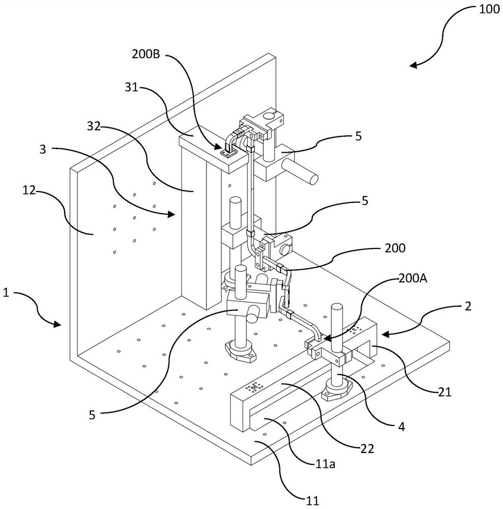
[0027] The waveguide feeder in the embodiment of the present invention is strip-shaped, has two ends with waveguide flanges, and is a component formed by connecting a plurality of waveguides with a clamp in the middle.

[0028]

[0029] This embodiment provides a waveguide feeder testing and welding device 100, which is used to fix the waveguide feeder 200 to be tested so as to perform electrical performance testing, welding and dimension inspection. At the end of the flange, the waveguide feeder is connected to external electrical performance testing equipment, and the electrical performance testing equipment has a first coaxial flange and a second coaxial flange for connecting the waveguide feeder to be tested.

[0030] In this embodiment, the electrical performance testing equipment is Yanetics.

[0031] figure 1 It is a structu...


PUM


Abstract

The invention provides a waveguide feeder testing and welding device, which belongs to the technical field of waveguide feeders, and is used for fixing a waveguide feeder to be tested, and the waveguide feeder is connected with external electrical performance testing equipment. The device is characterized by comprising a right-angled flat plate having a first flat plate arranged in the horizontaldirection anda second flat plate arranged in the vertical direction; a first adapter arranged on the first flat plate and used for adapting a first waveguide flange and a first test flange; a second adapter arranged on one surface, opposite to the first flat plate, of the second flat plate and used for adapting a second waveguide flange and a second test flange; and at least one limiting mechanismarranged on the right-angled flat plate and used for fixing the waveguide feeder. A plurality of fixing holes are evenly and densely distributed in the first flat plate and the second flat plate respectively, the limiting mechanism is detachably and fixedly connected to the right-angle flat plate through the fixing holes, the first adapter is provided with a first switching hole, and the second adapter is provided with a second switching hole.

Description

technical field [0001] The invention belongs to the field of waveguide feeder technology, and in particular relates to a waveguide feeder test welding device. Background technique [0002] In high-frequency radar systems, in order to reduce insertion loss and increase gain, waveguide components are widely used. In practical applications, in order to reduce the volume and weight increase caused by the flange, flangeless waveguide connections have been gradually adopted. At present, most of the flangeless waveguide components used in engineering use welding to realize the connection between waveguide feeders. Whether the final product can meet the performance index requirements depends on whether the welding process is qualified. At present, the performance indicators of the blue waveguide are mostly tested after the waveguide feeder is processed and then connected to the electrical performance testing equipment. [0003] However, the method of welding each section of the wa...

Claims


Application Information

Patent Timeline
Patent Type & Authority Applications(China)
IPC IPC(8): G01R1/04G01R31/00G01B21/00H01P11/00B23K13/00
CPCB23K13/00G01B21/00G01R1/0408G01R1/0416G01R31/00H01P11/005
Inventor 郝曼曼印小忠黄凯洮张嘉伟邹勤善
Owner 中电科微波通信(上海)股份有限公司
Why Eureka
Try Eureka